Current Sensor Error Compensation

a current sensor and error compensation technology, applied in the direction of electronic commutation motor control, motor/generator/converter stopper, dynamo-electric converter control, etc., can solve the problems of torque ripple and/or acoustic noise, torque degraded by the motor, unwanted torque ripple at the motor output sha

Active Publication Date: 2013-05-02
TRW LIMITED
View PDF44 Cites 80 Cited by
  • Summary
  • Abstract
  • Description
  • Claims
  • Application Information

AI Technical Summary

Problems solved by technology

Due to inaccuracies and limitations of the current sensor the measurement process can introduce harmonics into the output signal of the current sensor that are not present in the currents that are being measured.
Depending on the frequency and amplitude of these unwanted harmonics the torque produced by the motor can be degraded, with the harmonics potentially causing torque ripple and / or acoustic noise.
This will lead to unwanted torque ripple at the motor output shaft.

Method used


Image

  • Current Sensor Error Compensation
  • Current Sensor Error Compensation
  • Current Sensor Error Compensation

Examples


Embodiment Construction

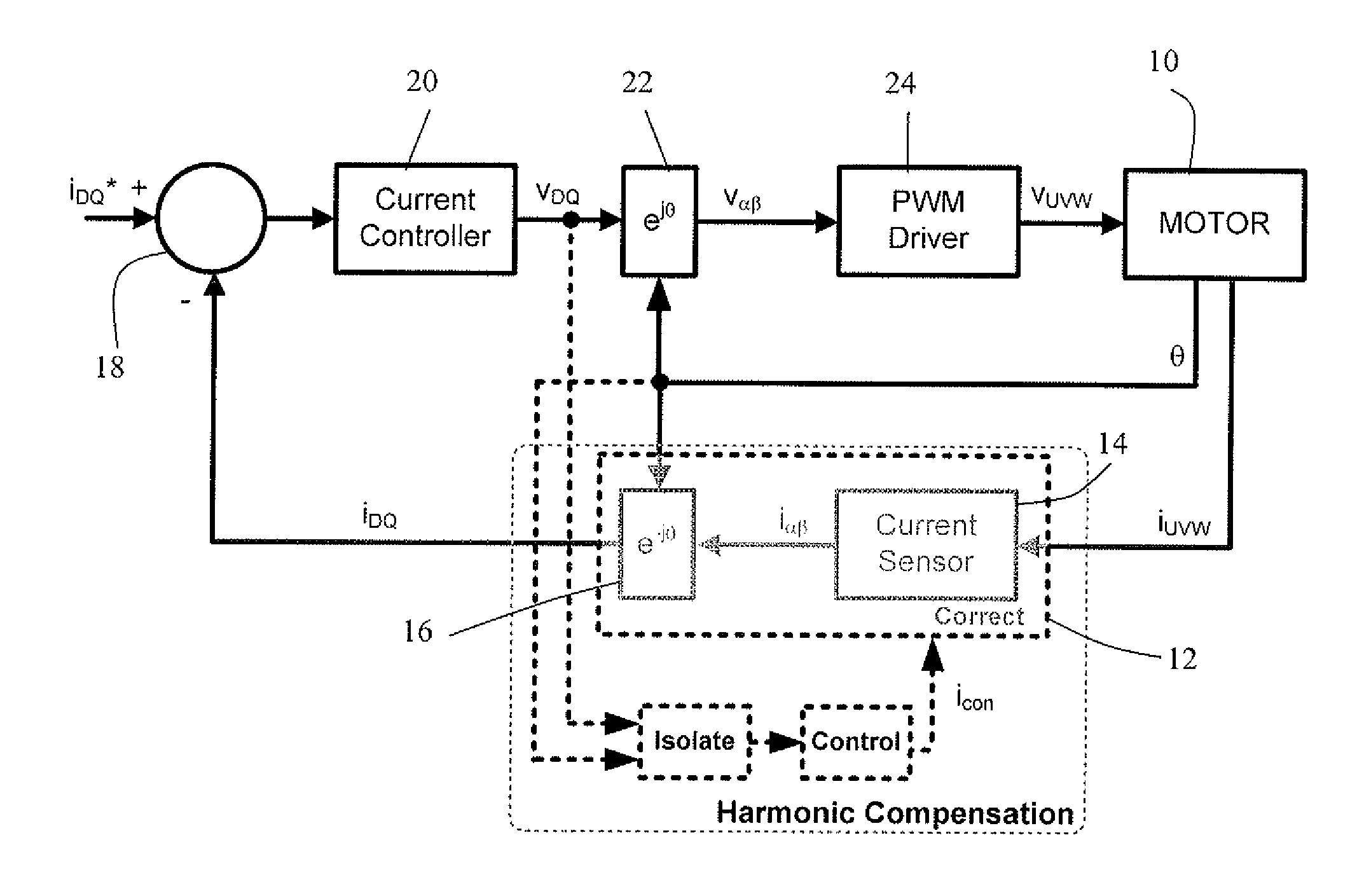
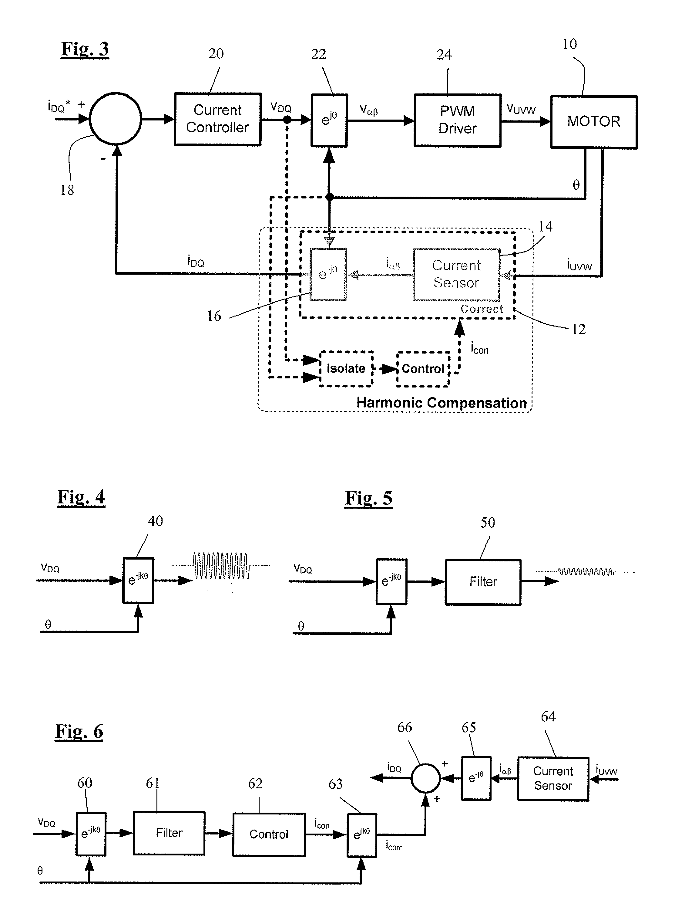
[0029]Referring to FIG. 3 a motor 10 is controlled by a closed loop motor current control system according to an embodiment of the invention comprises a current sensing system 12 and a current controller 20. A current sensing system 12 comprises a current sensor 14 arranged to measure the currents iU, iV, iw in the three phases of the motor, which comprise stationary windings, and output a signal indicative of the current vector in the stationary coordinates having α and β components. The current sensing system further comprises a coordinate transformation block 16 arranged to convert the current vector from the α and β components in the stationary reference from, to D and Q components iD and iQ defining the current vector in the rotor reference frame, which rotates relative to the fixed windings, with the Q axis current being the torque generating component and the D axis current being non-torque-generating. A comparator 18 receives the D and Q currents from the current sensing sys...


PUM


Abstract

A control system for an electric motor comprises a current sensing means arranged to produce a current sensing output indicative of electric current in the motor, current control means arranged to receive the current sensing output and to output a voltage demand indicative of voltages to be applied to the motor, and current sensing correction means arranged to monitor the voltage demand to measure distortion in the current sensing output and to generate a correction signal which is arranged to correct the distortion.

Description

CROSS-REFERENCE TO RELATED APPLICATIONS[0001]This application is a national stage of International Application No. PCT / GB2011 / 050303 filed Feb. 16, 2011, the disclosures of which are incorporated herein by reference in entirety, and which claimed priority to Great Britain Patent Application No. GB 1003456.9 filed Mar. 2, 2010, the disclosures of which are incorporated herein by reference in entirety.BACKGROUND OF THE INVENTION[0002]The present invention relates to the control of electric motors, and in particular to measurement of current in electric motors and the control of electric motors based on current measurement.[0003]A closed loop current controller for an electric actuator typically takes the form shown in FIG. 1, where, using vector control, a voltage is applied to each phase winding of the motor and the resultant generated currents measured. The measured currents are then used by a controller, typically a PI, to control to the requested target current. A signal which giv...

Claims


Application Information

Patent Timeline
Patent Type & Authority Applications(United States)
IPC IPC(8): H02P6/10
CPCH02P21/00H02P21/0035H02P6/10H02P29/0038H02P21/05H02P21/22H02P29/50
Inventor WILLIAMS, CONNEL BRETTDIXON, CHRISTOPHER DAVIDHUXFORD, ROBERT JAMES
Owner TRW LIMITED
Why Eureka
Try Eureka