Image Measuring System

a technology of image measurement and measuring system, which is applied in the field of image measurement system, can solve the problems of complex maintenance or calibration, high equipment cost, etc., and achieve the effects of easy expansion of the luminous flux of the illumination light, easy expansion of the s/n of the retroreflection light, and easy capture of the object to be measured

Active Publication Date: 2013-05-02
KK TOPCON
View PDF5 Cites 2 Cited by
  • Summary
  • Abstract
  • Description
  • Claims
  • Application Information

AI Technical Summary

Benefits of technology

[0026]Further, according to the present invention, in the image measuring system, the light projection unit has a focus function. As a result, the irradiation point can be irradiated in a pinpoint manner, and the S / N of the retroreflection light can be increased.
[0027]Further, according to the present invention, in the image measuring system, the light projection unit has a luminous flux diameter expanding means for expanding a luminous flux of the illumination light. As a result, the illumination using the illumination light can be performed in the wide range, and capturing of an object to be measured can be facilitated.
[0028]Further, according to the present invention, in the image measuring system, the luminous flux diameter expanding means is a diffuser which is provided so as to be insertable into or removable from the light projection optical axis. As a result, the luminous flux of the illumination light can be easily expanded.
[0029]Furthermore, according to the present invention, in the image measuring system, the photodetection optical system has a power varying function of increasing a photodetecting magnification. As a result, the angular resolving power can be further improved.

Problems solved by technology

Although the image total station has exclusive distance measuring function and angle measuring function and can superimpose the distance measurement and angle measurement data on an acquired image, a structure of the total station is fundamental, and the structure is complicated, for example, the total station has a vertical rotation axis or a horizontal rotation axis, and requires an angle detector that detects a rotational angle of the vertical rotation axis and the horizontal rotation axis or the like, hence the total station is an expensive apparatus.
Further, although the 3D image scanner can instantaneously measure a distance of a point, the 3D laser scanner requires a special light source that emits, e.g., a pulse laser beam or the like, also requires a vertical rotation axis and a horizontal rotation axis like the total station, has a complicated structure, and has a problem that the maintenance or the calibration is complicated.

Method used


Image

  • Image Measuring System
  • Image Measuring System
  • Image Measuring System

Examples


first embodiment

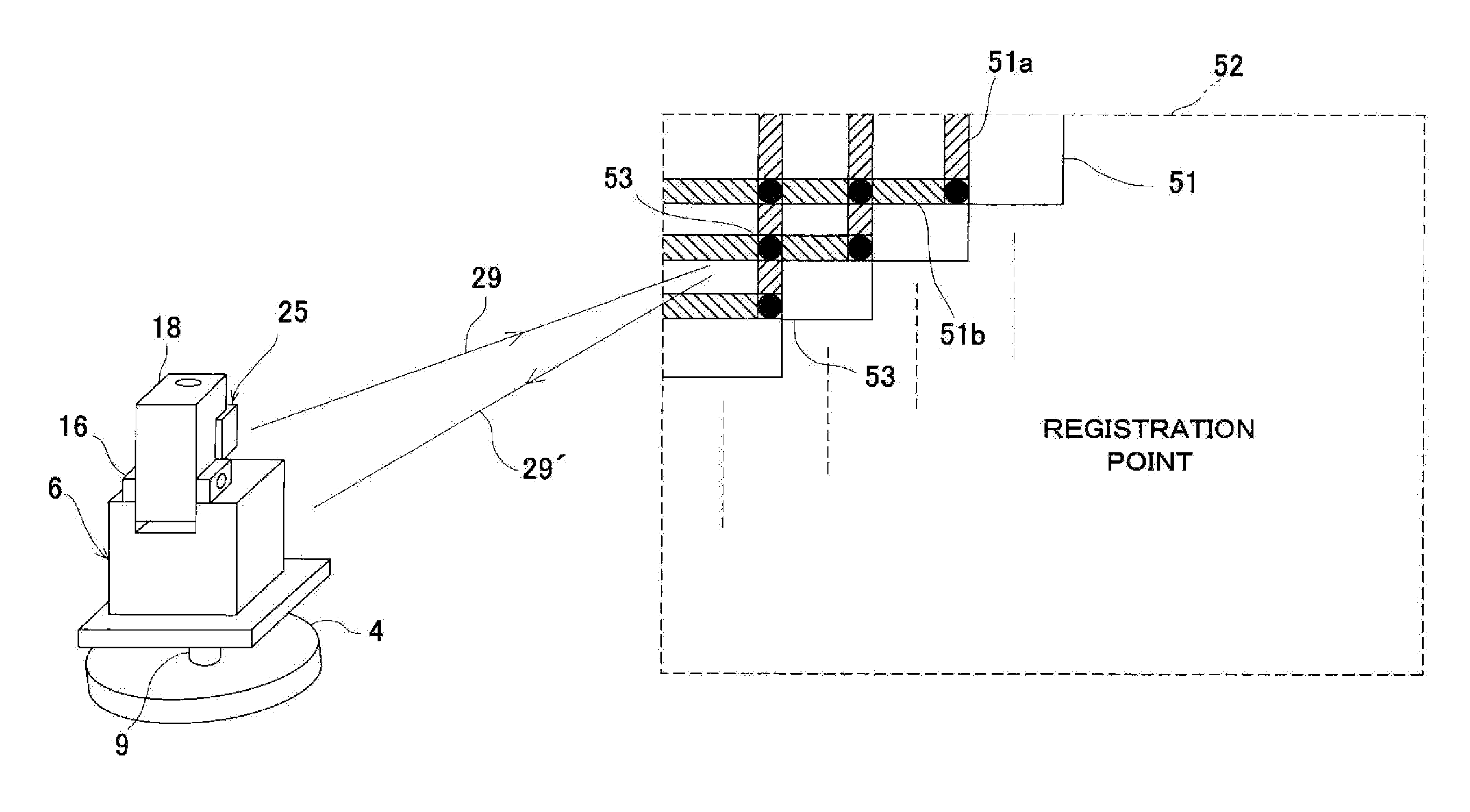
[0042]FIG. 1 shows an image measuring system 1 according to the present invention.

[0043]The image measuring system 1 is mainly constituted of a measuring system main unit 2, a leveling unit 3, and a rotary mechanism 4. The rotary mechanism 4 is provided on the leveling unit 3, and the measuring system main unit 2 is provided to the rotary mechanism 4 through a rotation axis 9. The leveling unit 3 has a leveling function that levels the measuring system main unit 2 to a horizontal posture through the rotary mechanism 4, and the rotary mechanism 4 has a function that rotationally moves the measuring system main unit 2 in the horizontal direction.

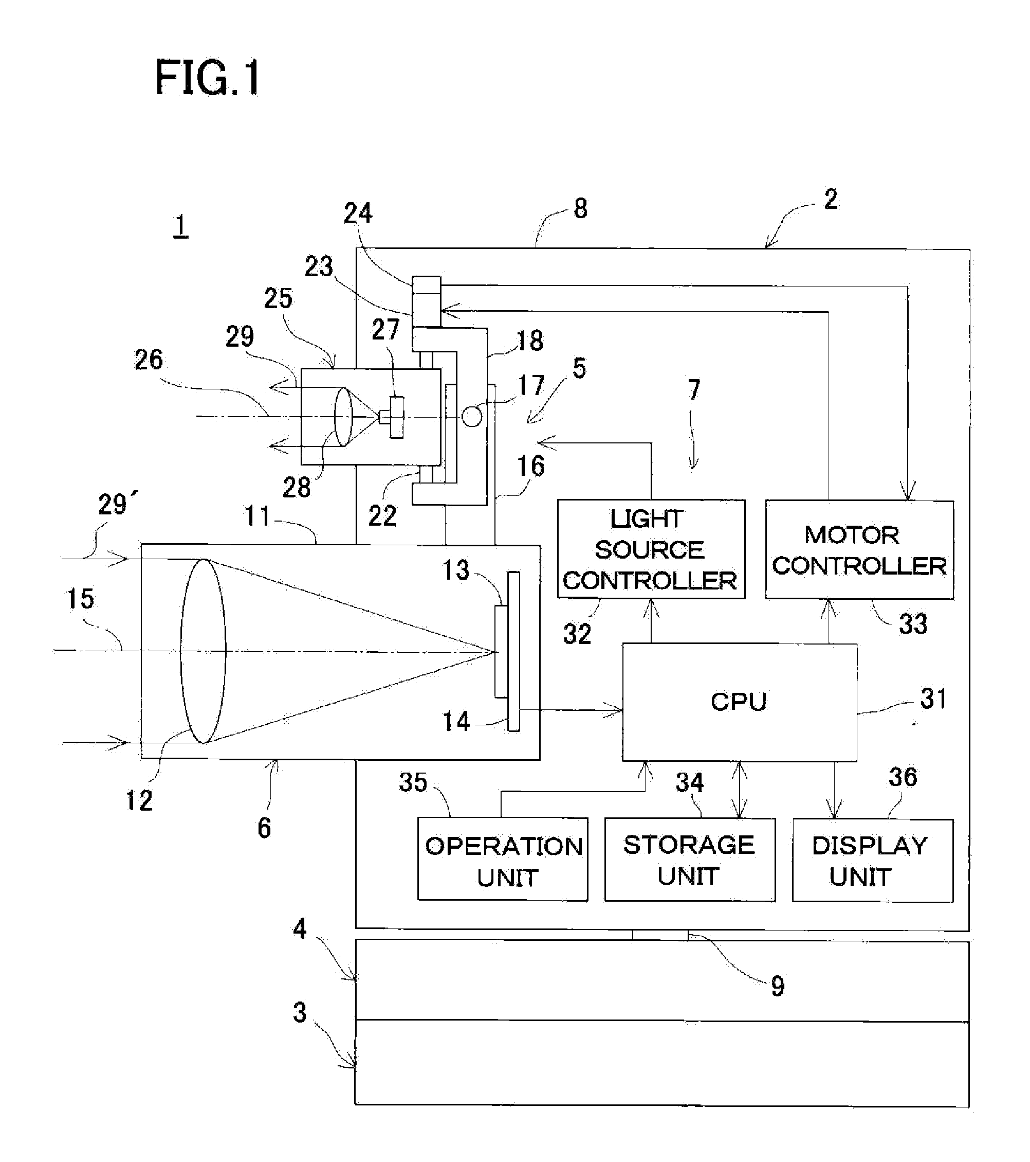
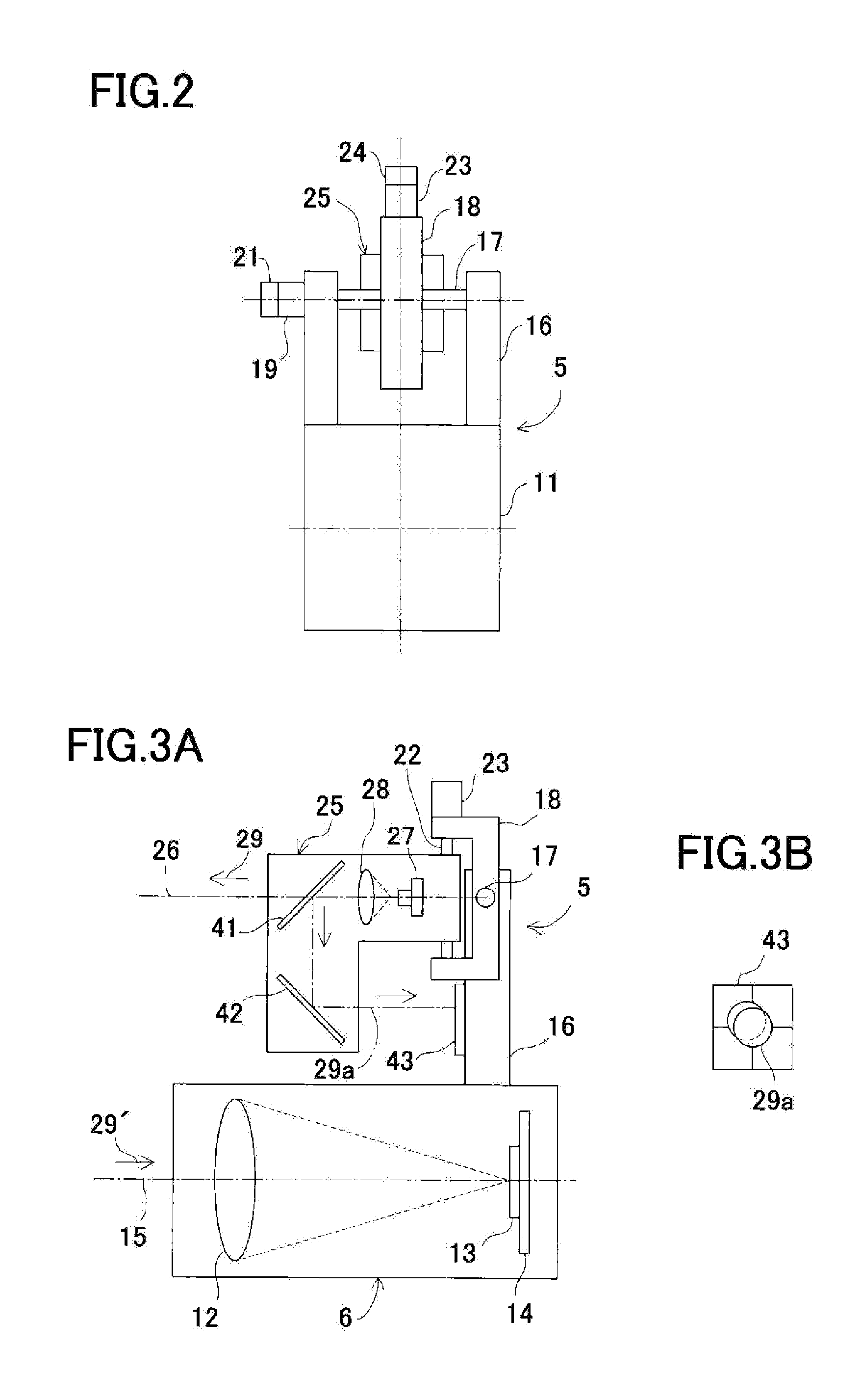
[0044]The measuring system main unit 2 comprises a projection optical system 5, a photodetection optical system 6, a control arithmetic device 7, and a casing 8, and the projection optical system 5, the photodetection optical system 6, and the control arithmetic device 7 are accommodated in the casing 8.

[0045]The photodetection optical system...

second embodiment

[0111]A second embodiment, when a distance image element is used as an image pickup element 13 in the foregoing embodiment, will now be described with reference to FIG. 1, FIG. 5, FIG. 6, and FIG. 8.

[0112]Here, the distance image element is constituted of many pixels, and it is possible to take the image of an object to be measured, to measure a time required for a light irradiated to the object to be measured to be received by the range image element after the reflection in accordance with each pixel, and to acquire a three-dimensional distance image in real time.

[0113]In the second embodiment, as a projection optical system 5, a function that enables expanding or contracting a luminous flux of an illumination light 29 (see FIG. 5 and FIG. 6) is provided, and as a photodetection optical system 6, a function that enables increasing or reducing the photodetecting magnification (see FIG. 8) is provided.

[0114]First, the luminous flux of the illumination light 29 is increased by the lum...


PUM


Abstract

An image measuring system comprises a projection optical system, having a light source for emitting and projecting an illumination light through a light projection optical axis. The system further comprises a photodetection optical system, having an image pickup element, which receives a retroreflection light from an object to be measured through a photodetection optical axis, and a control arithmetic device for processing the data taken by the image pickup element. The projection optical system comprises a light projection unit for directing the light projection optical axis toward the object to be measured and projecting the illumination light, a projection angle changing means for rotating the light projection unit in an elevating and a horizontal direction and for changing a projection angle of the illumination light, and a direction detecting means for detecting a direction angle of the light projection optical axis with respect to the photodetection optical axis.

Description

BACKGROUND OF THE INVENTION[0001]The present invention relates to an image measuring system for use in the indoor layout measurement or the measurement in the field of, e.g., the construction of buildings or the like.[0002]As a system that performs the measurement in a predetermined target area or the measurement of an object to be measured, the acquisition of an image of a target area or the acquisition of an image of the object to be measured, and the association of a measurement result and an image, there is an image total station or a 3D image scanner.[0003]Although the image total station has exclusive distance measuring function and angle measuring function and can superimpose the distance measurement and angle measurement data on an acquired image, a structure of the total station is fundamental, and the structure is complicated, for example, the total station has a vertical rotation axis or a horizontal rotation axis, and requires an angle detector that detects a rotational ...

Claims


Application Information

Patent Timeline
Patent Type & Authority Applications(United States)
IPC IPC(8): H04N7/18
CPCG01C15/002H04N7/18G01C11/06
Inventor KUMAGAI, KAORUKODAIRA, JUN-ICHI
Owner KK TOPCON
Why Eureka
Try Eureka