Wind turbine blade comprising a vortex-generator

a technology of turbine blades and generators, which is applied in the direction of wind energy generation, machines/engines, and final product manufacturing, etc., can solve the problems of unfavorable blade aerodynamic properties, time and cost, and the arrangement of blades and generators is expensive in time and cost, so as to achieve accurate positioning, reduce the effect of tolerances, and adjust the thickness of pain

Inactive Publication Date: 2013-05-02
SIEMENS AG
View PDF11 Cites 22 Cited by
  • Summary
  • Abstract
  • Description
  • Claims
  • Application Information

AI Technical Summary

Benefits of technology

[0041]Unwanted contributions of tolerances to aerodynamic properties of the blade (as described above) are reduced. It is possible in a easy way to adjust the thickness of paint by layers by well known and introduced methods. Thus the depth of the recess can be achieved quite easy and in a predictable manner, even in view to needed tolerances.
[0042]The vortex-generator-carrier-unit, which is shaped like a strip, increases the total adhered surface between the blade and the strip. Thus the strip is attached to the blade in a secure manner.
[0043]The vortex-generator-carrier-unit, which is shaped like a strip, allows a quite accurate positioning of the summarized vortex-generators.

Problems solved by technology

Thus careful and time-expensive work needs to be done by experienced workers to fix vortex generators at or into a blade as described above.
Thus the resulting blade-vortex-generator-arrangement and even the fixation method are quite expensive in time and in costs, too.

Method used


Image

  • Wind turbine blade comprising a vortex-generator
  • Wind turbine blade comprising a vortex-generator
  • Wind turbine blade comprising a vortex-generator

Examples


Embodiment Construction

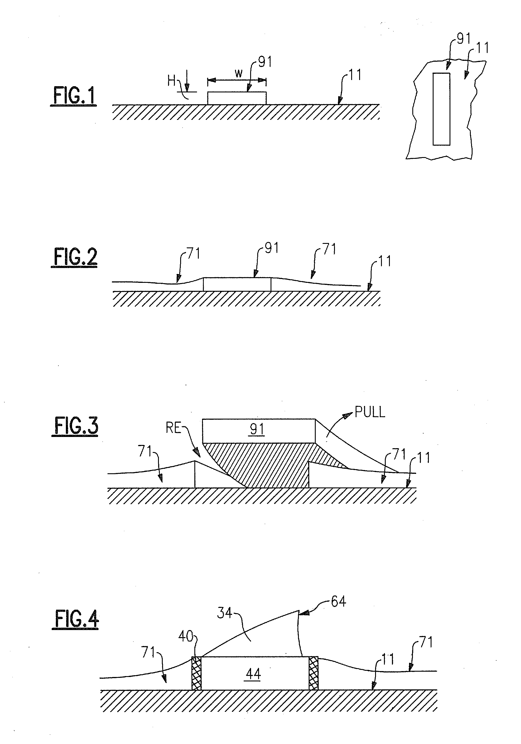
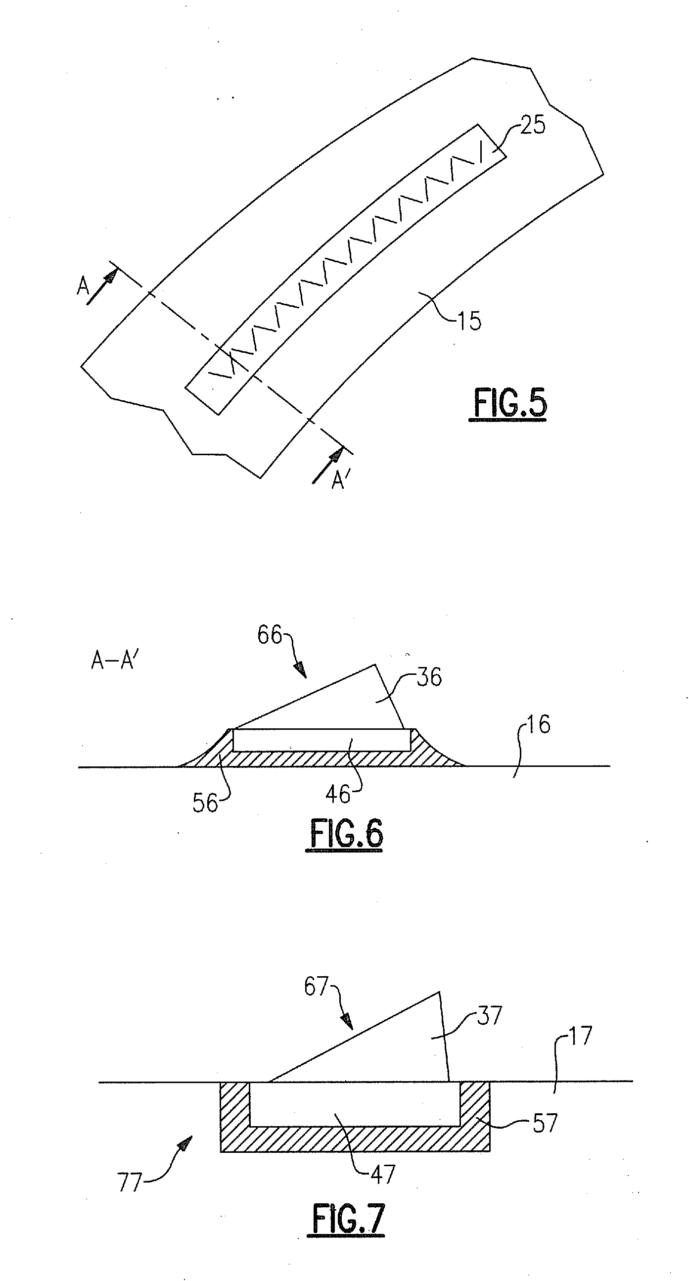
[0051]FIG. 1-FIG. 4 show in method steps, how the recess is prepared according to the invention and how vortex-generators are fixed therein finally.

[0052]FIG. 1 shows the side view and the top view of a blade 11. A former plate 91 is placed on top of the surface of the blade 11.

[0053]In this embodiment an adhesive tape 91 is used as former plate 91. The height H and the width W of the adhesive tape 91 corresponds to the dimensions of a recess, which is needed to fix a vortex generator there. This is shown later in FIG. 4.

[0054]FIG. 2 shows paint 71, which is applied in different layers to the surface of the blade 11.

[0055]In one embodiment a heating arrangement (i.e. an air-fan) is used to accelerate the curing of the painting 71.

[0056]FIG. 3 shows the removal of the adhesive tape 91. It is simply pulled away after the painting 71 was cured enough to allow this action without damages of the painting 71.

[0057]The adhesive tape 91 is pulled away as indicated by the arrow.
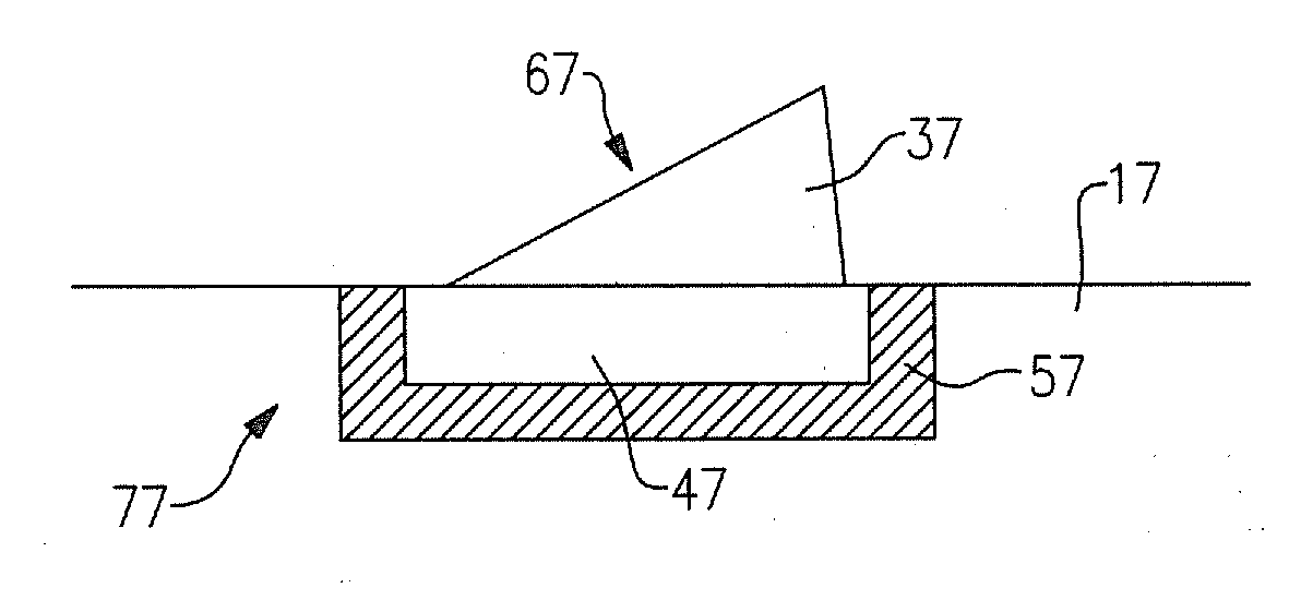
[0058]As show...


PUM

PropertyMeasurementUnit
aerodynamic characteristicsaaaaaaaaaa
rotational movementaaaaaaaaaa
lift coefficientaaaaaaaaaa

Abstract

A blade of a wind turbine and a method to manufacture the blade are provided. The blade of the wind turbine includes at least one vortex-generator. The vortex generator is constructed and arranged at the blade in a way that it contributes to the aerodynamic characteristics of the blade. The blade includes a recess, which is constructed and arranged to receive at least a part of the vortex-generator. The vortex generator is fixed in the recess. The recess is at least partly arranged and at least partly embedded in a layer of paint of the blade-surface. The recess is established by a former plate, which is arranged on the surface of the blade before the blade-surface is painted and while the recess is established by removing the former plate after the painting is finished.

Description

FIELD OF INVENTION[0001]The invention relates to a blade of a wind turbine, which comprises a vortex generator.BACKGROUND OF INVENTION[0002]It is known to use shaped devices to generate beneficial vortexes asides a wind turbine blade. These devices are known as “vortex generators”.[0003]The vortexes are used to influence the air flow along the surface of the wind turbine blade. For example the vortex generators are used to counteract the stall of air along the blade. Thus the rotational movement of the blade is improved by the generators.[0004]WO 0015961 A1 discloses a wind turbine blade, which is provided with a plurality of vortex generators. They project from the lee surface of the blade and are used to control a so called “boundary layer separation”.[0005]WO 2008113350 discloses an advantageous design of a wind turbine blade. The blade shows one or more parallel rows of sub-boundary layer vortex generators. The resulting blade is resistant to stall and a high maximum lift coeffi...

Claims


Application Information

Patent Timeline
Patent Type & Authority Applications(United States)
IPC IPC(8): F01D5/14B23P15/04
CPCF03D1/0641Y10T29/49321Y02E10/721F05B2240/122F05B2240/3062Y02E10/72Y02P70/50
Inventor THRUE, CARSTENKRISTENSEN, JENS JORGEN OSTERGAARDTANGAGER, KIMLAMBORN, CHAD
Owner SIEMENS AG
Why Eureka
Try Eureka