Voltage measurement

a technology of voltage measurement and measurement device, which is applied in the direction of resistance/reactance/impedence, power measurement by digital technique, instruments, etc., can solve the problems of insufficient accuracy, unknown impedance of the first impedance of the potential attenuator, and inability to extract modulation, so as to minimise the error in the determination of impedance, reduce the effect of error inducing effect and improving the ability to extract modulation

Active Publication Date: 2013-05-09
ANALOG DEVICES INT UNLTD
View PDF6 Cites 47 Cited by
  • Summary
  • Abstract
  • Description
  • Claims
  • Application Information

AI Technical Summary

Benefits of technology

[0034]Plural signal acquisitions may be made and one or more of various computations may be carried out in dependence on the signal acquisitions to, for example, take account of an alternating current signal being drawn from the source or to address noise. Therefore the impedance of the first impedance may be determined in dependence on at least one of plural first signal acquisitions and plural second signal acquisitions. The plural signals may be acquired over plural cycles of an alternating voltage signal between the first and second conductors. The processing arrangement may therefore be operative to reduce error inducing effects, such as impulsive noise. Alternatively or in addition the impedance of the first impedance may be determined in dependence on at least one of plural first signal acquisitions and plural second signal acquisitions within a cycle of an alternating voltage signal between the first and second conductors. More specifically the voltage measurement apparatus may be operative to determine in dependence on the plural signal acquisitions at least one of: an RMS voltage value for the alternating voltage signal; and a peak voltage value for the alternating voltage signal, such as an average peak voltage value.
[0035]Where an alternating voltage signal is present between the first and second conductors, the voltage measurement apparatus may be operative to change between the first and secon

Problems solved by technology

In addition the impedance of the first impedance of the potential attenuator may be unknown, may be known to insufficient accuracy or may have drifted from a known value during use.
As a result the attenuation factor, e.g. the potent

Method used


Image

  • Voltage measurement
  • Voltage measurement
  • Voltage measurement

Examples


first embodiment

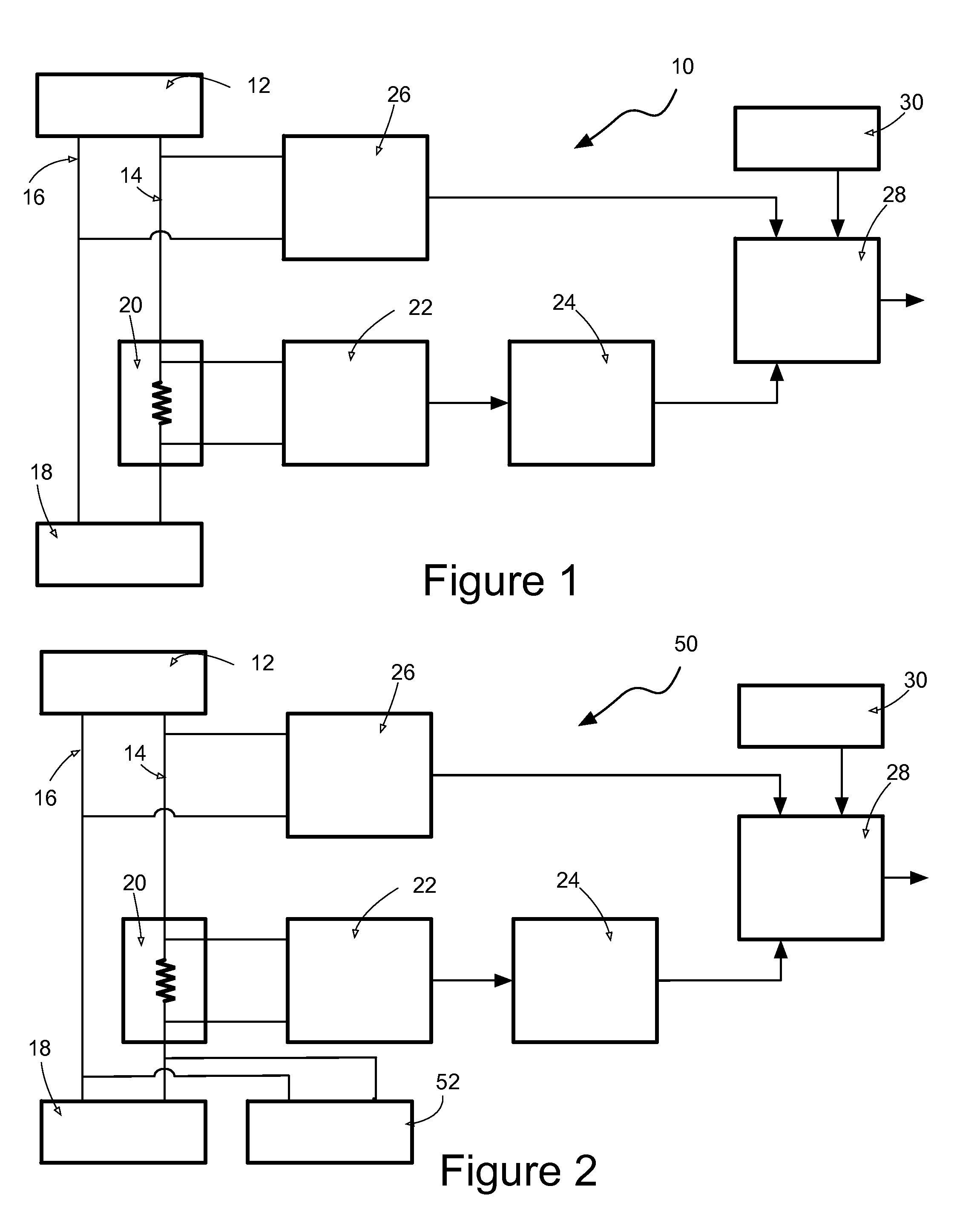
[0072]power measurement apparatus 10 is shown in FIG. 1.

[0073]The power measurement apparatus 10 forms part of an electricity consumption meter (not shown) installed at a point of supply to residential or business premises. A single phase mains alternating current electricity source 12 with live 14 and neutral 16 supply wires are shown in FIG. 1. Energy consuming apparatus at the residential or business premises is represented by a load 18. The power measurement apparatus 10 comprises a shunt resistor 20 of known resistance in the live supply wire 14 in series with the load 18 between the load and the electricity supply 12. The shunt resistor 20 presents a low value of resistance, such as a resistance of 1 mΩ. The power measurement apparatus 10 further comprises voltage measuring apparatus 22, signal processing circuitry 24 and voltage measurement apparatus 26. The voltage measurement apparatus 26 is described in detail below with reference to FIGS. 4A to 5C. Inputs to the voltage m...

second embodiment

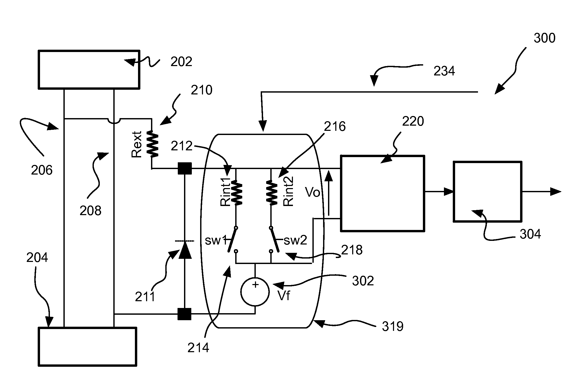
[0083]Voltage measurement apparatus 300 is shown in FIG. 4B. Components of the apparatus of FIG. 4B in common with FIG. 4A are designated with like reference numbers and the reader's attention is directed to the description provided above with reference to FIG. 4A for a description of such common components. The voltage measurement apparatus 300 of FIG. 4B further comprises an offset voltage circuit 302, which is electrically connected between the neutral wire 208 and the ends of the first and second switches 214, 218 opposite the second and third resistors 212, 216. The second and third resistors 212, 216, the first and second switches 214, 218 and the offset voltage circuit 302 together constitute a reference impedance arrangement 319. In addition the voltage measurement apparatus 300 comprises an offset voltage compensation circuit 304 which receives the output from the voltage digitisation circuitry 220 as an input. A protection diode 211 is present on the input of the integrat...

third embodiment

[0085]A first form of reference impedance arrangement 450 as an alternative to the reference impedance arrangement shown in FIG. 4C is shown in FIG. 4D. Differences between the first form of reference impedance arrangement 450 of FIG. 4D and the reference impedance arrangement 419 of FIG. 4C will now be described. The first form of reference impedance arrangement 450 comprises a signal generator 452 in series between the internal resistor 402 and the neutral wire instead of the first and second switches 414, 418 and the offset voltage circuit 404. The signal generator 452 is operative to apply a square wave voltage between the internal resistor 402 and the neutral wire to thereby provide for modulation between two offset voltage levels. Otherwise the operation of voltage measurement apparatus comprising the first form of reference impedance arrangement 450 is as described above with reference to FIG. 4C.

[0086]A second form of reference impedance arrangement 460 as an alternative to ...


PUM


Abstract

The present invention relates to voltage measurement apparatus. The voltage measurement apparatus comprises a potential attenuator configured to be electrically connected between first and second conductors, which are electrically coupled to a source. The potential attenuator comprises a first impedance and a reference impedance arrangement in series with each other. The reference impedance arrangement has an electrical characteristic which is changed in a known fashion. The voltage measurement apparatus further comprises a processing arrangement configured: to acquire at least one signal from the reference impedance arrangement, the at least one signal reflecting change of the electrical characteristic in the known fashion; and to determine a voltage between the first and second conductors in dependence on the fashion in which the electrical characteristic is changed being known and the at least one signal.

Description

CROSS REFERENCE TO RELATED APPLICATION[0001]This application claims priority to U.S. Provisional Application No. 61 / 557,369, filed on Nov. 8, 2011, which is incorporated herein by reference in its entirety as if fully set forth herein.FIELD OF THE INVENTION[0002]The present invention relates to voltage measurement apparatus and methods of measuring voltage, in particular but not exclusively for measuring line voltage in the like of electricity consumption circuits and electricity generation circuits. The present invention further relates to apparatus, such as electricity generation, transmission, distribution or consumption apparatus, which comprises such voltage measurement apparatus or is operative to measure voltage according to such methods. In particular but not exclusively current is measured in conjunction with voltage to provide for determination of at least one power metric.BACKGROUND ART[0003]Electromechanical meters have been long used to measure electricity consumed by r...

Claims


Application Information

Patent Timeline
IPC IPC(8): G01R27/08
CPCG01R21/133G01R21/14G01R19/02G01R15/04G01R35/04G01R19/0084
Inventor DANESH, SEYED AMIR ALIHURWITZ, JONATHAN EPHRAIM DAVID
Owner ANALOG DEVICES INT UNLTD
Why Eureka
Try Eureka