Switching Regulator and Control Circuit and Control Method Thereof

a technology of switching regulator and control circuit, which is applied in the direction of dc-dc conversion, climate sustainability, power conversion systems, etc., can solve the problems of increasing the cost, increasing the risk of indirect opto-coupling, and inability to detect signals related to output voltage and output current directly electrically connected to the control circui

Inactive Publication Date: 2013-05-09
RICHTEK TECH
View PDF5 Cites 26 Cited by
  • Summary
  • Abstract
  • Description
  • Claims
  • Application Information

AI Technical Summary

Benefits of technology

[0025]In another embodiment, the control method for controlling the switching regulator may further include: detecting a timing when an output current of the switching regulator is zero to generate a zero current detection signal; and adjusting the control signal according to the zero current detection signal to determine a boundary conduction timing.
[0026]In another e...

Problems solved by technology

One of the drawbacks of the aforementioned prior art is that, the detected signals related to the output voltage and the output current can not be directly electrically connected to a control circuit in an isolated switching regulator, such as an isolated AC/DC con...

Method used


Image

  • Switching Regulator and Control Circuit and Control Method Thereof
  • Switching Regulator and Control Circuit and Control Method Thereof
  • Switching Regulator and Control Circuit and Control Method Thereof

Examples


first embodiment

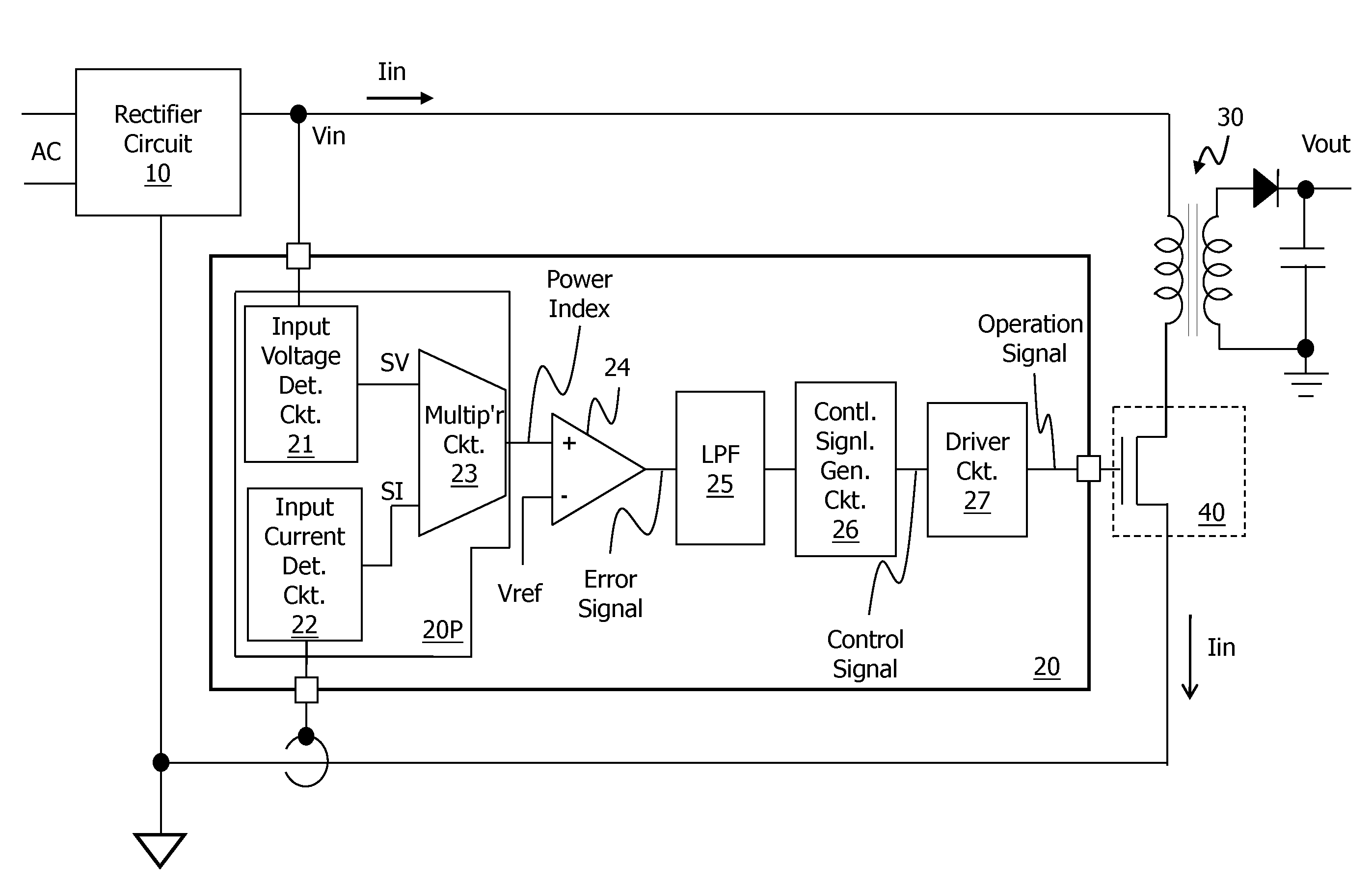
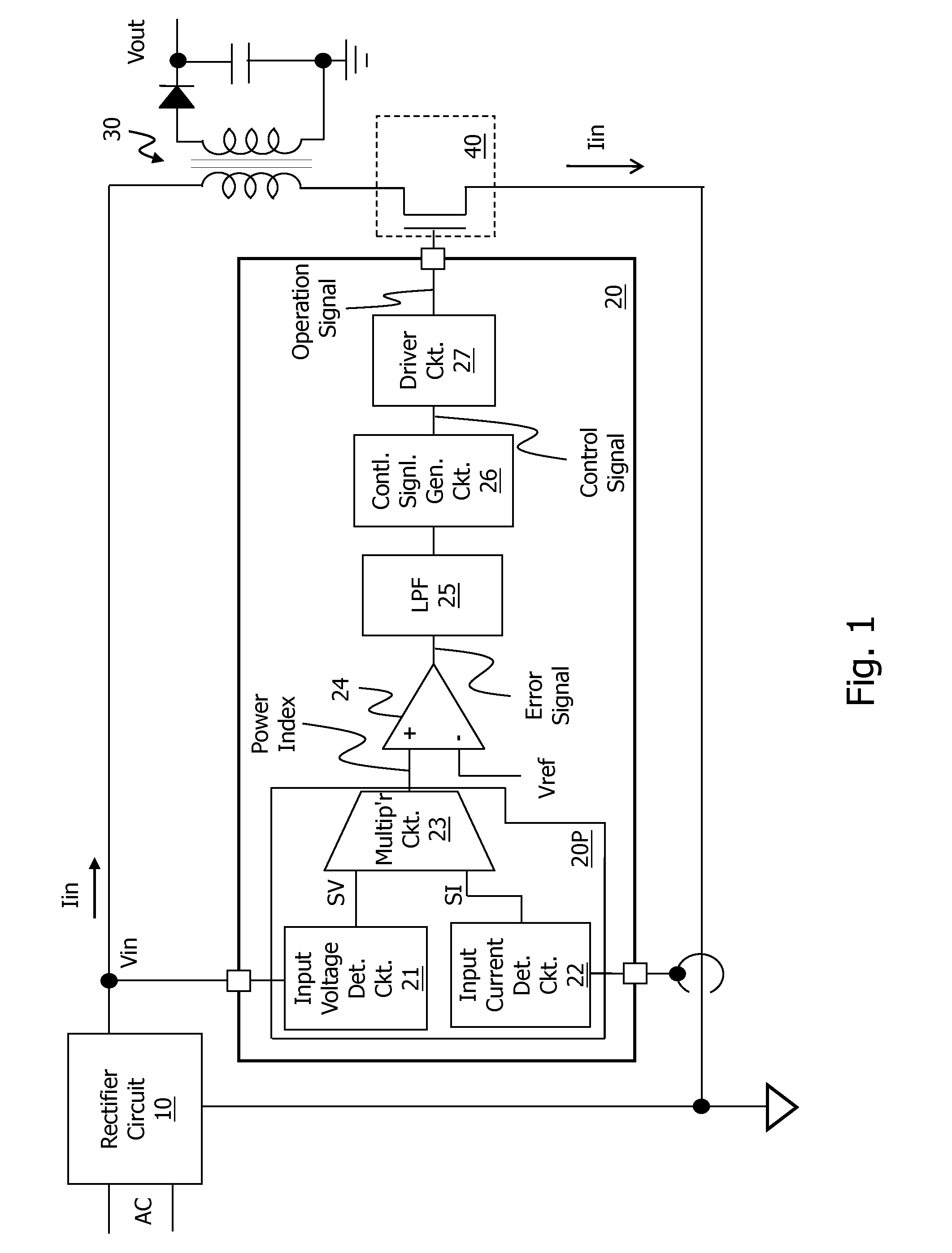
[0036]FIG. 1 shows the present invention. As shown in the figure, a switching regulator includes a rectifier circuit 10, a control circuit 20, a transformer 30, and a power switch 40. The rectifier circuit 10 is for example but not limited to abridge rectifier circuit (not shown in detail), for converting an AC power with positive and negative sinusoidal waves to a rectified power with only positive semi-sinusoidal waves, wherein the rectified power includes an input voltage Vin and an input current Iin. The transformer 30 includes a primary winding and a secondary winding, wherein the primary winding receives the rectified power, and the secondary winding generates an output voltage Vout. The power switch 40 is coupled to the primary winding, and it switches according to an operation signal outputted from the control circuit 20, such that the rectified power is converted to the output voltage Vout. The control circuit 20 can control the rectified power within a predetermined range....

sixth embodiment

[0040]FIG. 4 shows the present invention. This embodiment is different from the first embodiment in that, the control circuit 100 of this embodiment further includes a modulation circuit, which is for example but not limited to a multiplier circuit 51 as shown in the figure. The multiplier circuit 51 receives a voltage detection signal SV2 and the error signal, and multiplies them to generate a modulated error signal. The voltage detection signal SV2 is, for example but not limited to, the same as the voltage detection signal SV. The control signal generation circuit 26 for example receives the modulated error signal and a second current detection signal SI2, to generate the control signal. The second current detection signal SI2 is, for example but not limited to, the same as the current detection signal SI.

[0041]Note that the multiplier circuit 51 and the control signal generation circuit 26 form a power factor correction (PFC) circuit 50. The function of the multiplier circuit 51...


PUM


Abstract

The present invention discloses a switching regulator and a control circuit and a control method thereof. The control circuit of the switching regulator, which controls rectified power within a predetermined range, detects an input voltage and an input current to generate a voltage detection signal and a current detection signal respectively, and the voltage detection signal and the current detection signal are multiplied by one the other to generate a power index. The control circuit generates an error signal according to the power index and a reference signal. A low-pass-filter filters a high frequency band in the process. A control signal generation circuit of the control circuit generates a control signal according to the error signal. And a driver circuit of the control circuit generates an operation signal according to the control signal, for switching a power switch to convert the rectified power to an output voltage.

Description

CROSS REFERENCE[0001]The present invention claims priority to TW 100144137, filed on Dec. 1, 2011.BACKGROUND OF THE INVENTION[0002]1. Field of Invention[0003]The present invention relates to a switching regulator, and a control circuit and method for controlling a switching regulator. Particularly, it relates to such switching regulator, control circuit, and control method which control a rectified power (an input power after rectification) within a predetermined range.[0004]2. Description of Related Art[0005]The output power or output current of a switching regulator is preferably controlled within a predetermined range in some applications of the switching regulator. To control the output power or output current within a predetermined range, in prior art, it is required to detect the output voltage and the output current and feedback such information to control the switching regulator.[0006]One of the drawbacks of the aforementioned prior art is that, the detected signals related ...

Claims


Application Information

Patent Timeline
IPC IPC(8): H02M3/335
CPCH02M3/33507Y02B70/126H02M1/4258Y02B70/10
Inventor LIAO, CHIA-WEILIU, JING-MENGHSIU, LENG-NIENCHEN, PEI-YUAN
Owner RICHTEK TECH
Why Eureka
Try Eureka