Receiver, integrated circuit, receiving method, and program

Active Publication Date: 2013-05-09
PANASONIC CORP
View PDF1 Cites 30 Cited by
  • Summary
  • Abstract
  • Description
  • Claims
  • Application Information

AI Technical Summary

Benefits of technology

[0011]According to the above-mentioned aspect, by calculating the interference power on the basis of the number of samples exceeding the predetermined threshol

Problems solved by technology

However, PTL 1 fails to mention a specific method of calculating the noise power in units of symbol.
Since impulse noise occurs in an impulse manner from, for example, pow

Method used


Image

  • Receiver, integrated circuit, receiving method, and program
  • Receiver, integrated circuit, receiving method, and program
  • Receiver, integrated circuit, receiving method, and program

Examples


first embodiment

[0106]First embodiment of a receiver from one aspect of the present invention will be described below with reference to FIG. 1 to FIG. 6. The DVB-T2 scheme as the 2nd-generation European terrestrial digital broadcasting standard is used herein as an example.

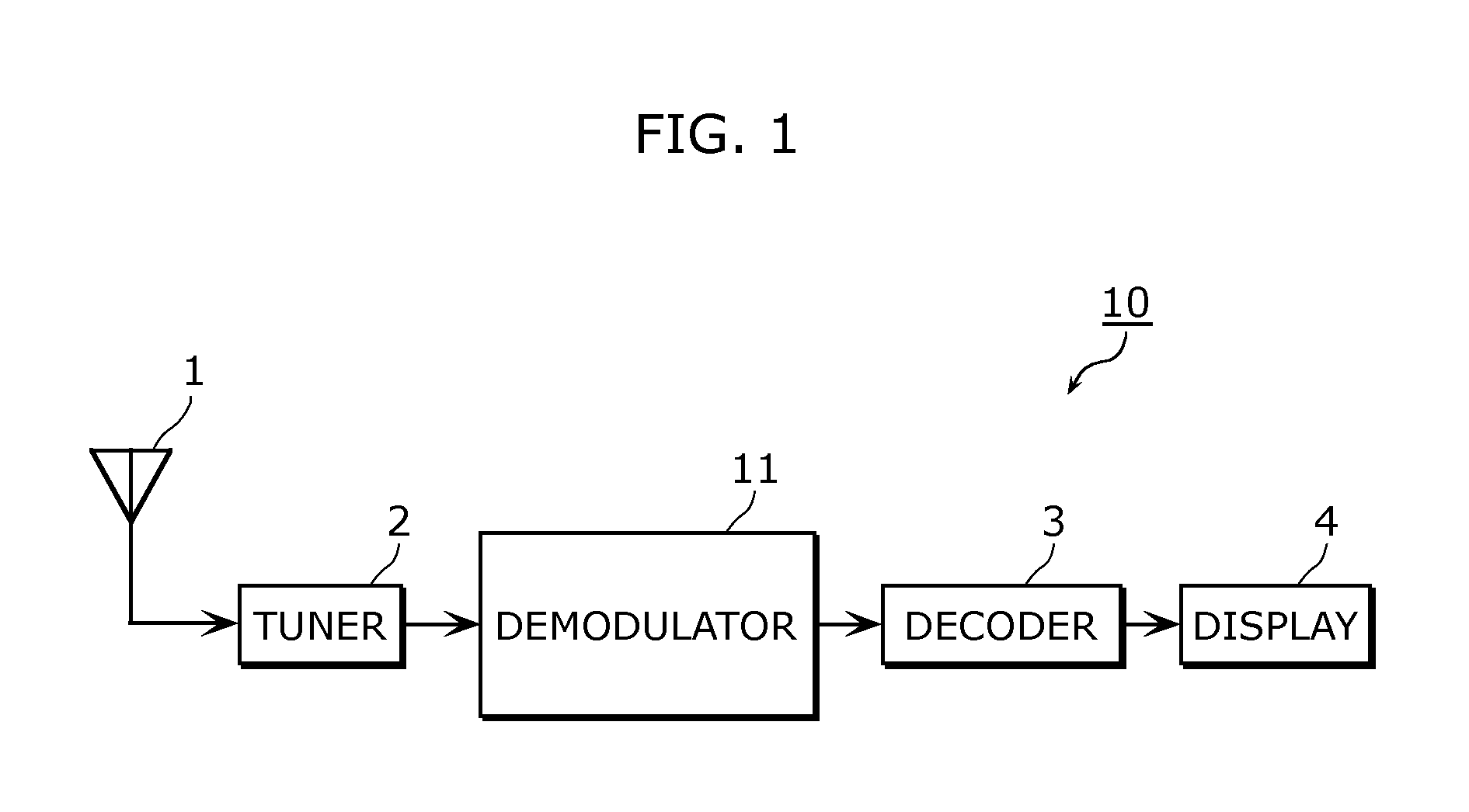
[0107]FIG. 1 is a block diagram showing a receiver 10 in First embodiment of the present invention. The receiver 10 includes an antenna 1, a tuner 2, a demodulator 11, a decoder 3, and a display 4.

[0108]The antenna 1 receives a modulation wave modulated according to orthogonal frequency division multiplexing (OFDM). Airwave based on the DVB-T2 scheme is an example of the modulation wave modulated according to the orthogonal frequency division multiplexing (OFDM).

[0109]The tuner 2 selects a received signal of a desired reception channel from the modulation wave received by the antenna 1.

[0110]The demodulator 11 demodulates the received analog signal selected by the tuner 2.

[0111]The decoder 3 decodes the signal that is demodulated...

second embodiment

[0151]A receiver in accordance with Second embodiment of the present invention will be described below with reference to FIG. 7 to FIG. 10. The same components as those in FIG. 1 to FIG. 6 are given the same reference numerals and description thereof is omitted.

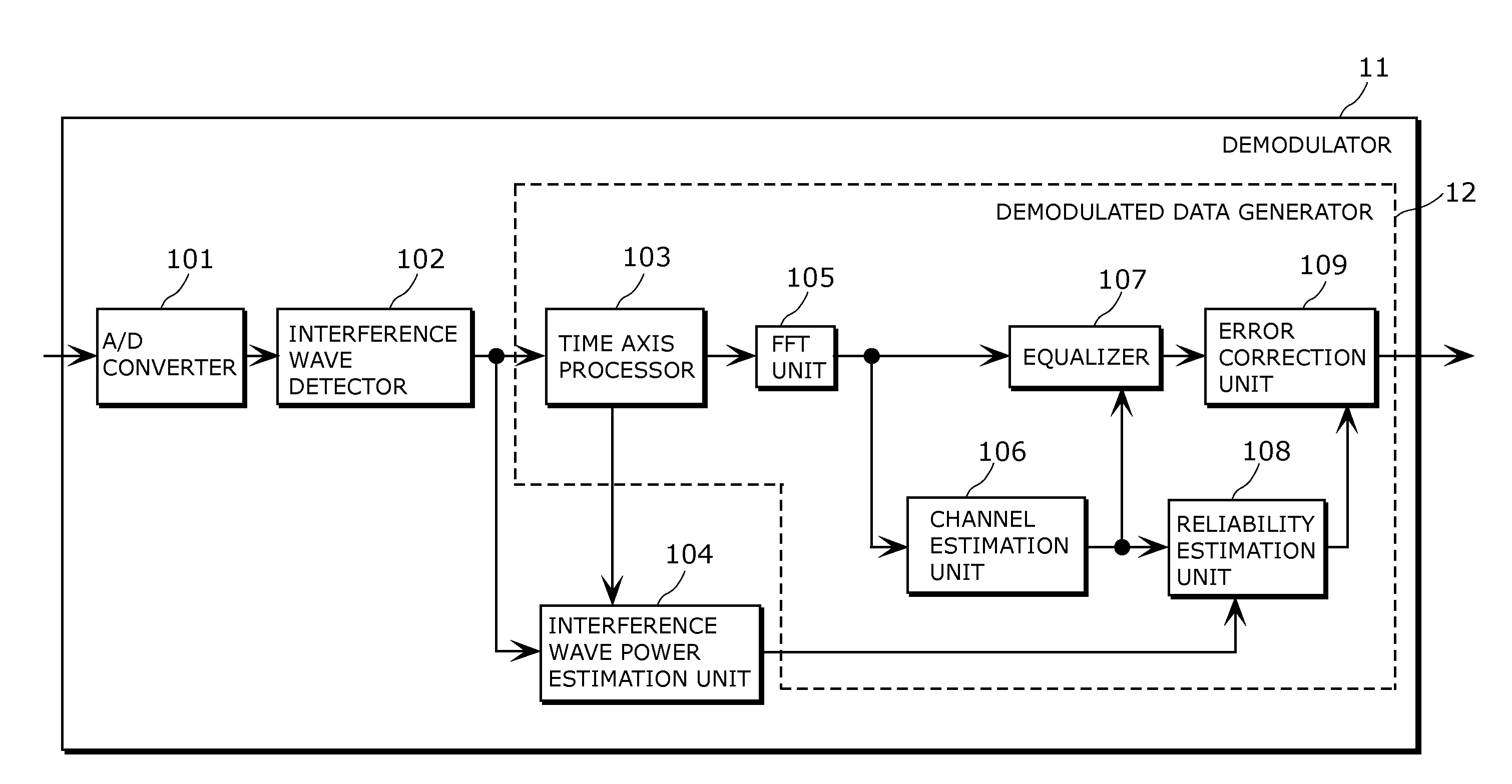
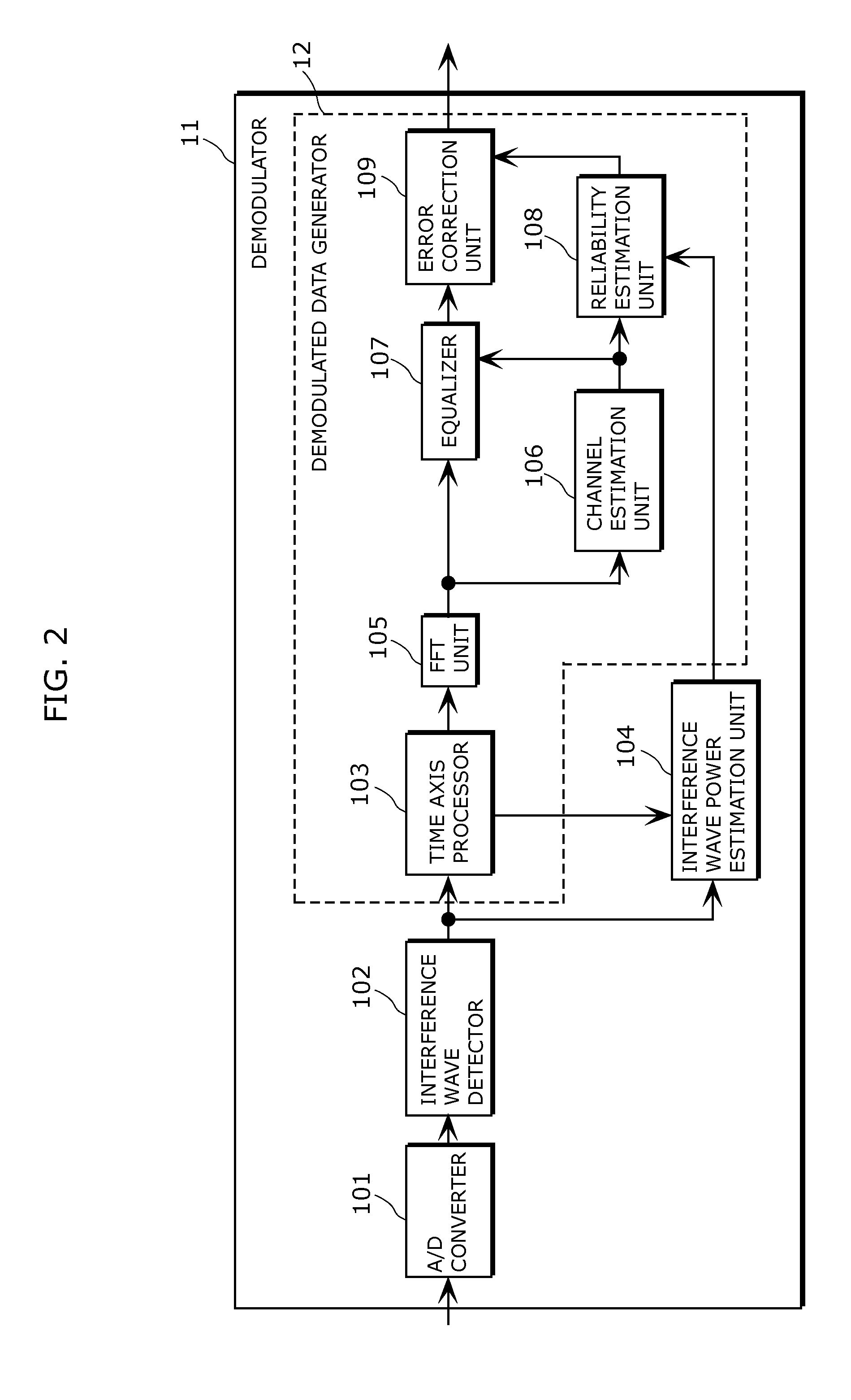
[0152]FIG. 7 is a block diagram showing a receiver 20 in accordance with Second embodiment of the present invention, and FIG. 8 is a block diagram showing a configuration of a demodulator 21. FIG. 8 is different from FIG. 2 only in an interference wave detector 202 and an interference wave power estimation unit 204.

[0153]FIG. 9 is a view showing a configuration of the interference wave detector 202. The interference wave detector 202 includes an interference wave sample detector 211 and a clip processor 212.

[0154]Like the interference wave sample detector 111 in First embodiment, the interference wave sample detector 211 compares a received signal converted into a digital signal by an A / D converter with a predetermined thresh...

third embodiment

[0164]A receiver in accordance with Third embodiment of the present invention will be described below with reference to FIG. 11 to FIG. 14A. The same components as those in FIG. 1 to FIG. 6 are given the same reference numerals and description thereof is omitted.

[0165]FIG. 11 is a block diagram showing a receiver 30 in accordance with Third embodiment of the present invention, and FIG. 12 is a block diagram showing a configuration of a demodulator 31. The demodulator 31 shown in FIG. 12 is different from the demodulator 11 in First embodiment in a configuration of an interference wave power estimation unit 304.

[0166]FIG. 13 is a view showing the configuration of the interference wave power estimation unit 304. The interference wave power estimation unit 304 includes an interference wave sample counter 131, an interference power converter 132, a second interference power converter 332, and an adder 333. The interference wave power estimation unit 304 corresponds to a second interfere...


PUM


Abstract

A receiver includes a demodulator that demodulates a modulation wave modulated according to orthogonal frequency division multiplexing (OFDM). The demodulator includes an interference wave detector that detects that received modulation wave includes interference wave when received power of each sample of the received modulation wave exceeds a threshold, and upon the detection, executes replacement processing of replacing a received signal exceeding the threshold with a predetermined value, a first interference wave power estimation unit configured to estimate interference wave power included in an OFDM symbol included in the received modulation wave on the basis of the number of samples that have been subjected to the replacement processing, and a demodulated data generator that demodulates the received modulation wave by executing demodulation processing of demodulating the received modulation wave that has been subjected to the replacement processing on the basis of the interference wave power.

Description

TECHNICAL FIELD[0001]The present invention relates to a receiver, an integrated circuit, a receiving method, and a program, and in particular, to a receiver, an integrated circuit, a receiving method, and a program that are provided with a demodulator for demodulating a modulation wave modulated according to orthogonal frequency division multiplexing (OFDM).BACKGROUND ART[0002]In various types of current digital communication such as terrestrial digital broadcasting, IEEE802.11a and the like, orthogonal frequency division multiplexing (OFDM) has been widely adopted as a transmission method.[0003]An exemplary OFDM receiver generates reliability information by using calculated noise power, and utilizes the reliability information to enable high-accuracy error correction using an LDPC (Low Density Parity Check) code (for example, PTL 1). According to the technique disclosed in PTL 1, specifically, for noise power calculated from pilot signals or an OFDM band spectrum, average noise pow...

Claims


Application Information

Patent Timeline
IPC IPC(8): H04L12/26H04J11/00
CPCH04L25/022H04L25/0232H04L27/2662H04L27/2691H04L5/005H04L2025/03414H04J11/0036H04L1/0047H04L43/0823H04N17/004
Inventor MURAKAMI, MARIKOMATSUMURA, YOSHINOBU
Owner PANASONIC CORP
Why Eureka
Try Eureka