Telescoping screw for femoral neck fractures

a telescopic screw and femoral neck technology, applied in the field of bone fracture treatment devices, can solve problems such as complicated procedures

Active Publication Date: 2013-05-09
DEPUY SYNTHES PROD INC
View PDF1 Cites 11 Cited by
  • Summary
  • Abstract
  • Description
  • Claims
  • Application Information

AI Technical Summary

Benefits of technology

[0004]The present invention is directed to a system for treating a bone, which includes a bone fixation device. The bone fixation device includes a first element extending along a first longitudinal axis from a proximal end to a distal end, the first element including a first channel extending therethrough along the first longitudinal axis and a second element extending along a second longitudinal axis from a proximal end to a distal end, the second element including a proximal portion sized and shaped to be received within the first channel such that the first and second longitudinal axes are substantially coaxial and a distal portion including a bone engaging structure, a proximal end of the second element sli

Problems solved by technology

These stops, however, require a three piece assembly or a wel

Method used


Image

  • Telescoping screw for femoral neck fractures
  • Telescoping screw for femoral neck fractures
  • Telescoping screw for femoral neck fractures

Examples


Embodiment Construction

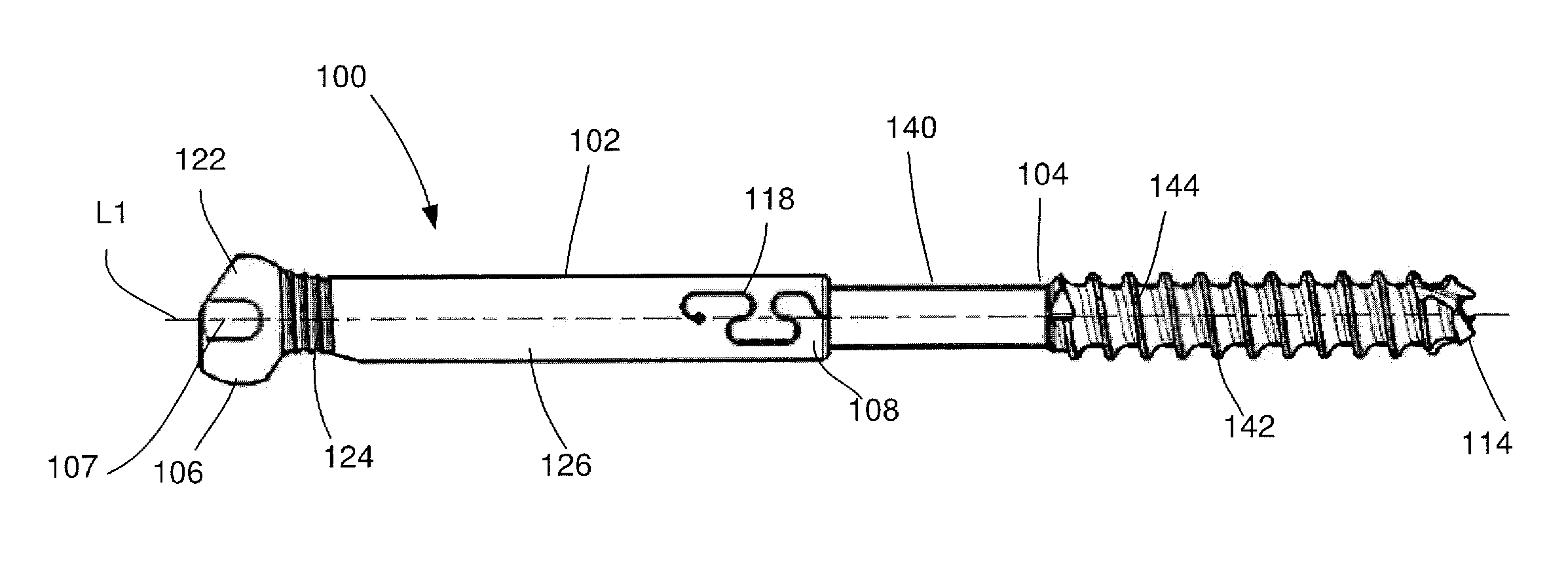
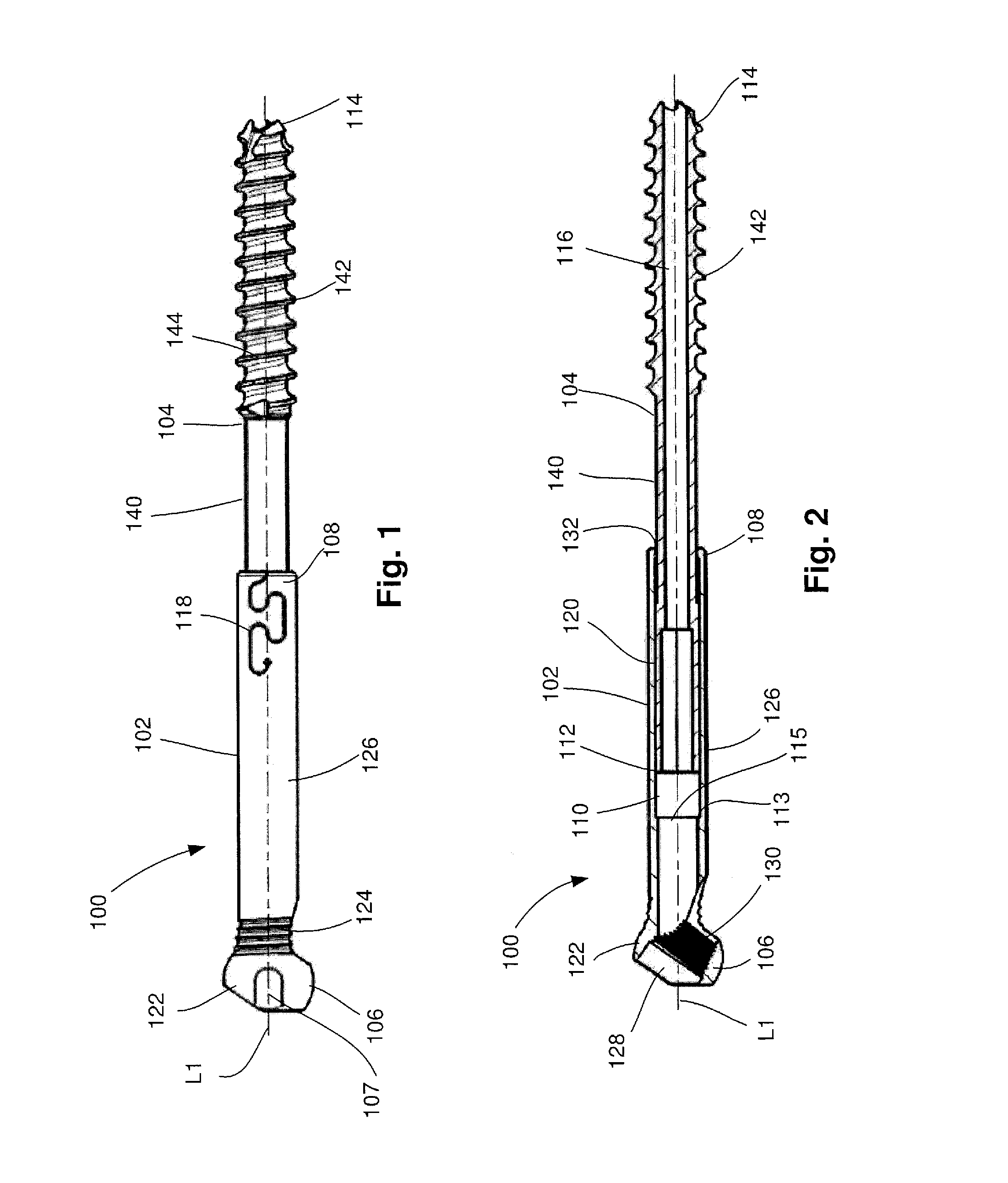
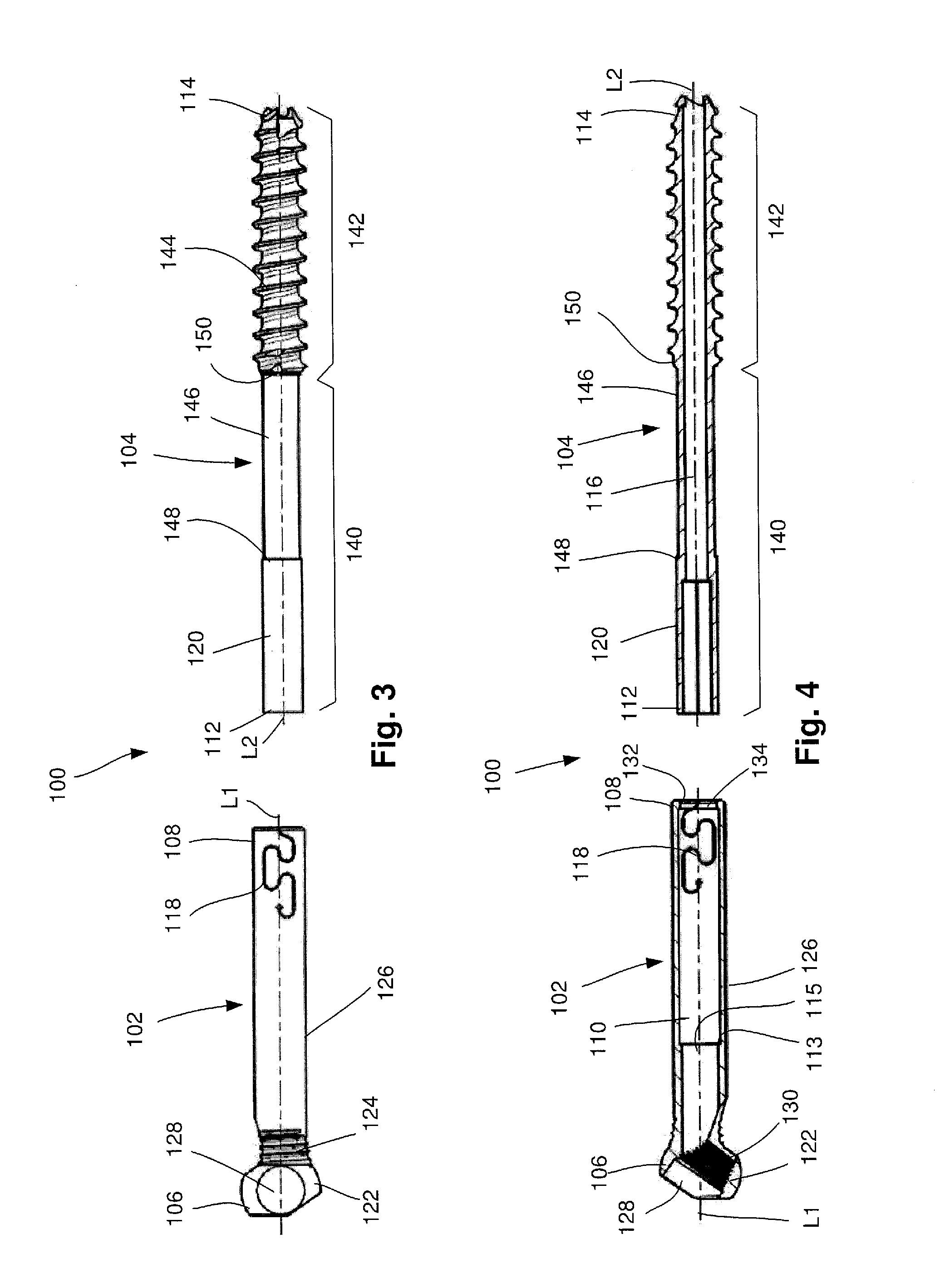
[0051]The present invention may be further understood with reference to the following description and the appended drawings, wherein like elements are referred to with the same reference numerals. The present invention relates to devices for treating a bone and, in particular, devices for treating bone fractures. An exemplary embodiment of the present invention describes a bone fixation device including first and second elements configured to telescope with respect to one another within a predetermined range of motion. It should be noted that the terms “proximal” and “distal” as used herein, are intended to refer to a direction toward (proximal) and away from (distal) a user of the device.

[0052]A system 100 according to an exemplary embodiment of the present invention comprises a bone fixation device 101, as shown in FIGS. 1-6, including a first element 102 and a second element 104 received within the first element 102 such that the first and second elements 102, 104 telescope longi...


PUM


Abstract

A bone fixation system includes a bone fixation device, including a first element having a first channel extending therethrough and a second element including a proximal portion sized and shaped to be received within the first channel such that the longitudinal axes of the first and second elements are substantially coaxial and a distal portion including a bone engaging structure, a proximal end of the second element slidably locked within the first channel such that the first and second elements are longitudinally movable relative to one another between a permitted range of motion. The system also includes a driving tool, including an outer sleeve and an inner sleeve slidably received therethrough, a distal end of the outer sleeve configured to engage the proximal end of the first element to prevent relative rotation therebetween, a distal end of the inner sleeve configured to engage the proximal end of the second element.

Description

PRIORITY CLAIM[0001]The present invention claims priority to U.S. Provisional Application Ser. No. 61 / 487,140 filed on May 17, 2011 and entitled “Telescoping Screw for Femoral Neck Fractures,” the entire disclosure of which is incorporated herein by reference.FIELD OF THE INVENTION[0002]The present invention relates to devices for treating a bone and, in particular, devices for treating bone fractures. An exemplary embodiment of the present invention describes a bone fixation device including first and second elements configured to telescope with respect to one another within a predetermined range of motion.BACKGROUND[0003]Telescoping screws have been used to fix various types of fractures and, in particular, have been employed to fix femoral neck fractures. Telescoping screws are particularly useful for fixing femoral neck fractures since the telescoping feature permits migration of the implanted screw while preventing the screw tip from penetrating the hip joint which is a signifi...

Claims


Application Information

Patent Timeline
IPC IPC(8): A61B17/74
CPCA61B17/74A61B17/8894A61B17/8872A61B17/746A61B17/742A61B17/88A61B17/86
Inventor ZURSCHMIEDE, SILAS
Owner DEPUY SYNTHES PROD INC
Why Eureka
Try Eureka