System and method for changing when a vehicle enters a vehicle yard

a technology for changing the position of a vehicle and a vehicle yard, applied in the field of transportation networks, can solve the problems of one or more vehicles falling behind their associated schedules, insufficient room for the additional locomotive and car of the train, and inability to fit into a rail yard

Inactive Publication Date: 2013-05-09
GENERAL ELECTRIC CO
View PDF31 Cites 28 Cited by
  • Summary
  • Abstract
  • Description
  • Claims
  • Application Information

AI Technical Summary

Benefits of technology

[0010]In another embodiment, another system includes a monitoring module and a scheduling module. The monitoring module is configured to track a capacity of a vehicle yard in a transportation network to receive vehicles for layover in the vehicle yard over time. The scheduling module is configured to determine an updated time of entry for a first vehicle to enter the vehicle yard based on the capacity of the vehicle yard at the updated time of entry. The scheduling module is configured to communicate the updated time of entry to the first vehicle so that the first vehicle can change speed as the first vehicle moves toward the vehicle yard.

Problems solved by technology

But, due to unforeseen circumstances, such as damage to routes in the transportation network, unplanned maintenance to one or more vehicles, accidents, and the like, one or more vehicles may fall behind their associated schedules.
Falling behind the schedules can cause the vehicles to enter into and / or leave a vehicle yard at a different time than previously scheduled.
For example, a train having one or more locomotives and several cars may be unable to fit into a rail yard when other locomotives, cars, or other vehicles are in the rail yard and there is not enough room to receive the additional locomotive and cars of the train.
As a result, the vehicle waiting to enter the vehicle yard may waste resources such as time, fuel, and / or operator time, and / or generate additional emissions while waiting for the capacity of the vehicle yard to increase.

Method used


Image

  • System and method for changing when a vehicle enters a vehicle yard
  • System and method for changing when a vehicle enters a vehicle yard
  • System and method for changing when a vehicle enters a vehicle yard

Examples


Embodiment Construction

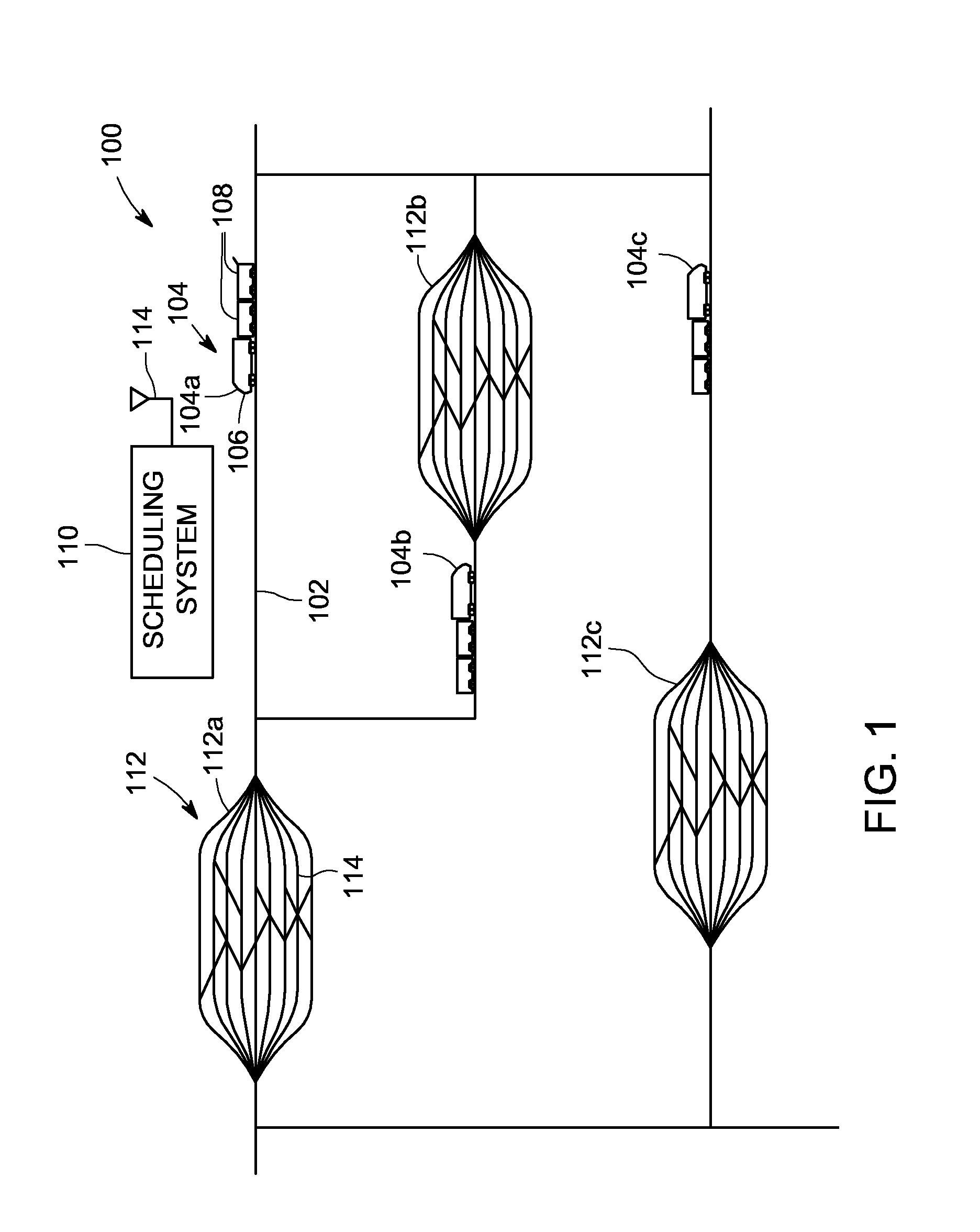
[0022]One or more embodiments of the inventive subject matter described herein provide systems for coordinating arrival of a vehicle moving toward a vehicle yard with a capacity of the vehicle yard to receive the vehicle. The vehicle may travel to the vehicle yard to be stored at the vehicle yard (e.g., to end a current trip of the vehicle and remain at the vehicle yard), for repair and / or maintenance of the vehicle, to obtain additional fuel, to unload cargo and / or cars off of the vehicle, to load cargo and / or cars onto the vehicle, to sort the vehicle among other vehicles (e.g., to rearrange an order of the vehicles such that the vehicles leave the vehicle yard in a designated order), or the like. The vehicle yard may act as a transportation hub in a transportation network, such as when the vehicle yard is coupled with several routes extending away from the vehicle yard for the vehicles to travel along to reach other destinations. The vehicle yard may be a final destination of a t...


PUM


Abstract

A system includes a control unit that is configured to be disposed on-board a first vehicle that moves along a route of a transportation network having a vehicle yard. The control unit also is configured to receive, from off-board the first vehicle, an updated time of entry into the vehicle yard for the approaching vehicle and to change a speed of the first vehicle in response to the updated time of entry. A method includes receiving an updated time of entry into a vehicle yard at a first vehicle that is moving along a route of a transportation network that includes the vehicle yard and changing a speed of the first vehicle in response to the updated time of entry. The updated time is received from off-board the first vehicle.

Description

BACKGROUND[0001]A transportation network for vehicles can include several interconnected main routes on which separate vehicles travel between locations. For example, a transportation network may be formed from interconnected railroad tracks with rail vehicles traveling along the tracks. The vehicles may travel according to schedules that dictate where and when the vehicles are to travel in the transportation network. The schedules may be coordinated with each other in order to arrange for certain vehicles to arrive at various locations in the transportation network at desired times and / or in a desired order.[0002]The transportation network can include a vehicle yard, such as a rail yard that includes a relatively dense grouping of routes or locations where several vehicles can congregate. As the vehicles travel through the transportation network, one or more vehicles may travel to a vehicle yard for storage, maintenance, refueling, reordering with other vehicles, and the like. The ...

Claims


Application Information

Patent Timeline
Patent Type & Authority Applications(United States)
IPC IPC(8): G05D1/00
CPCB61L3/006B61L17/00B61L2205/04B61L27/0027B61L25/025B61L27/16
Inventor COOPER, JAREDSAMUELS, MASON
Owner GENERAL ELECTRIC CO
Why Eureka
Try Eureka