Robot arm assembly

a robot arm and assembly technology, applied in the field of industrial robots, can solve the problems of complicated and space-consuming robot arm assemblies

Inactive Publication Date: 2013-05-16
HONG FU JIN PRECISION IND (SHENZHEN) CO LTD +1
View PDF7 Cites 19 Cited by
  • Summary
  • Abstract
  • Description
  • Claims
  • Application Information

AI Technical Summary

Problems solved by technology

This result is the robot arm assembly is more complicated and space consuming.

Method used


Image

  • Robot arm assembly
  • Robot arm assembly
  • Robot arm assembly

Examples


Embodiment Construction

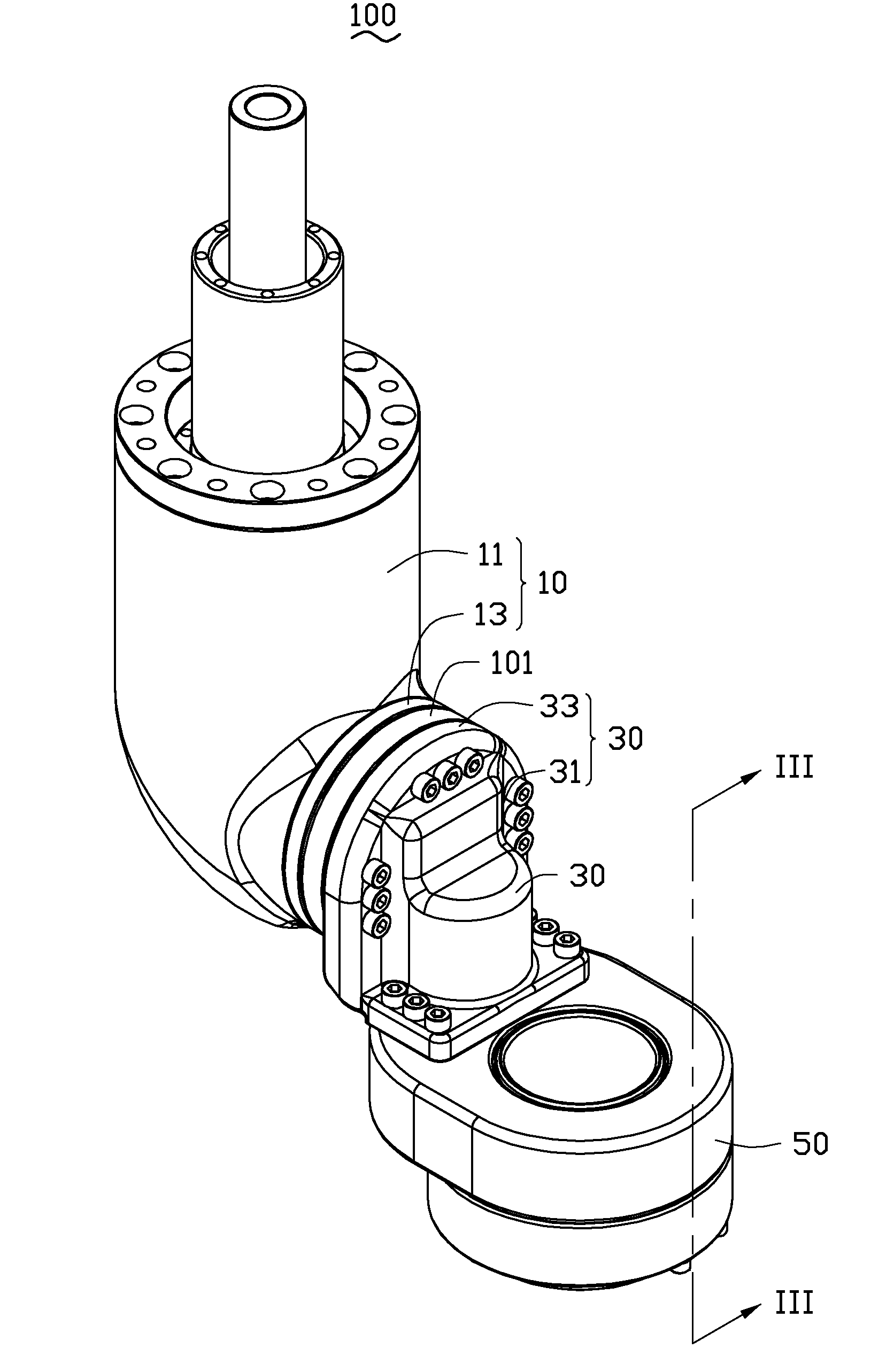
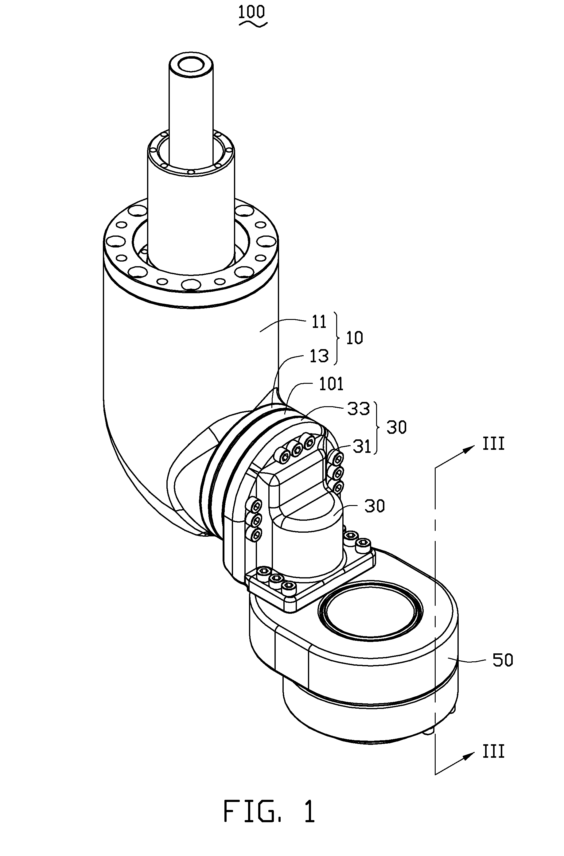
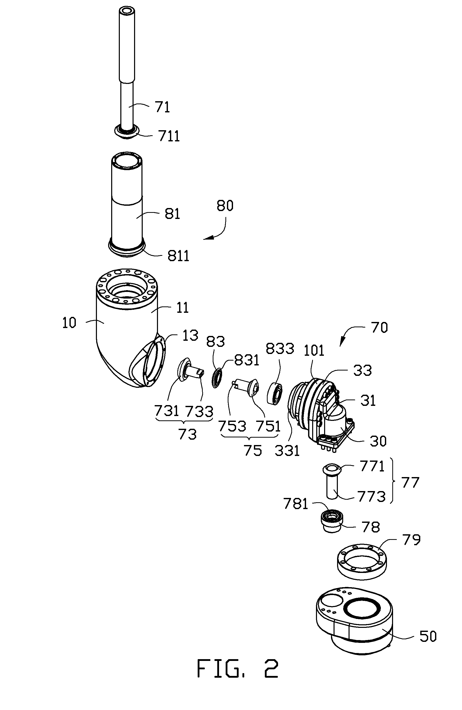
[0010]FIGS. 1 and 3, illustrate an embodiment of a robot arm assembly 100 used in six-axis industrial robot. The robot arm assembly 100 includes a first mechanical arm 10, a second mechanical arm 30, a third mechanical arm 50, a first transmission assembly 70, and a second transmission assembly 80. The first mechanical arm 10, the second mechanical arm 30, and the third mechanical arm 50 are rotatably connected together in that order, such that, the second mechanical arm 30 is assembled between the first mechanical arm 10 and the third mechanical arm 50. The third mechanical arm 50 is configured for mounting a tool (not shown) such as a fixture, a gripper, a cutting tool, for example. The first mechanical arm 10, the second mechanical arm 30 and the third mechanical arm 50 are respectively configured to rotate along a first axis A, a second axis B and a third axis C of the six-axis robot. In the embodiment, the first axis A and the third axis C are substantially parallel, and substa...


PUM


Abstract

A robot arm assembly includes a first mechanical arm, a second mechanical arm, a third mechanical arm, a first transmission assembly and a second transmission assembly. The first mechanical arm, the second mechanical arm and the third mechanical arm are rotatably connected together in that order, and are respectively configured to rotate along a first axis A, a second axis B and a third axis C. The first transmission assembly is assembled within the first mechanical arm and the second mechanical arm, and is further coupled with the third mechanical arm. The second transmission assembly is assembled within the first mechanical arm and sleeved on the first transmission assembly, the second transmission assembly is further coupled with the second mechanical arm.

Description

BACKGROUND[0001]1. Technical Field[0002]The present disclosure relates to an industrial robot, and more particularly, to a robot arm assembly of the industrial robot.[0003]2. Description of Related Art[0004]A commonly used industrial robot includes a plurality of arms rotatably connected to each other in order, thus, a movement of multiple axis is achieved. For example, a driving member is assembled between the first mechanical arm and the second mechanical arm to drive the second mechanical arm to rotate with respect to the first mechanical arm. Therefore, a number of driving members should be assembled between arms if the manipulator has many arms. Thus, the driving members are scattered between the arms of robot arm assembly. This result is the robot arm assembly is more complicated and space consuming.[0005]Therefore, there is room for improvement within the art.BRIEF DESCRIPTION OF THE DRAWINGS[0006]The components in the drawings are not necessarily drawn to scale, the emphasis...

Claims


Application Information

Patent Timeline
Patent Type & Authority Applications(United States)
IPC IPC(8): B25J18/00
CPCY10T74/20305B25J17/0283
Inventor LONG, BO
Owner HONG FU JIN PRECISION IND (SHENZHEN) CO LTD
Why Eureka
Try Eureka