Fluid transfer assembly and methods of fluid transfer

a technology of fluid transfer and assembly, applied in the direction of valve housing, packaging goods type, application, etc., can solve the problems of wasting liquid, increasing the foam of carbonated beverages, requiring extra serving time and attention, etc., and achieve the effect of reducing the potential for stale liquid

Active Publication Date: 2013-05-16
GRINON INDS
View PDF4 Cites 42 Cited by
  • Summary
  • Abstract
  • Description
  • Claims
  • Application Information

AI Technical Summary

Benefits of technology

[0006]In one embodiment, the dispensing system may include a flushing system. The flushing system may remove liquid from the dispenser connection device after a container is removed. Removing the liquid may reduce the potential for stale liquid to accumulate in the dispenser connection device between fillings. The flushing system may flush the dispenser connection device with a cleansing fluid, such as, for example, water, alcohol, or air to remove the liquid from the dispenser connection device between uses.
[0007]In one embodiment, a removal system permits rapid draining of a container through its bottom. The removal system may be coupled to the container connection device to permit rapid removal of the previously filled fluid of the container. The removal system may open a valve of the container connection device and create a fluid flow path from the container to the end of the removal system.

Problems solved by technology

However, filling a serving container from the top may increase foam of carbonated beverages.
To reduce the foam, a user generally pours out the excess from the serving container, thereby wasting liquid.
Alternatively, a user may wait for the foam to settle, which requires extra serving time and attention.
Moreover, transfer devices for top filling methods often take a large amount of space on a counter or serving area, and require attention to operate and control.

Method used


Image

  • Fluid transfer assembly and methods of fluid transfer
  • Fluid transfer assembly and methods of fluid transfer
  • Fluid transfer assembly and methods of fluid transfer

Examples


Embodiment Construction

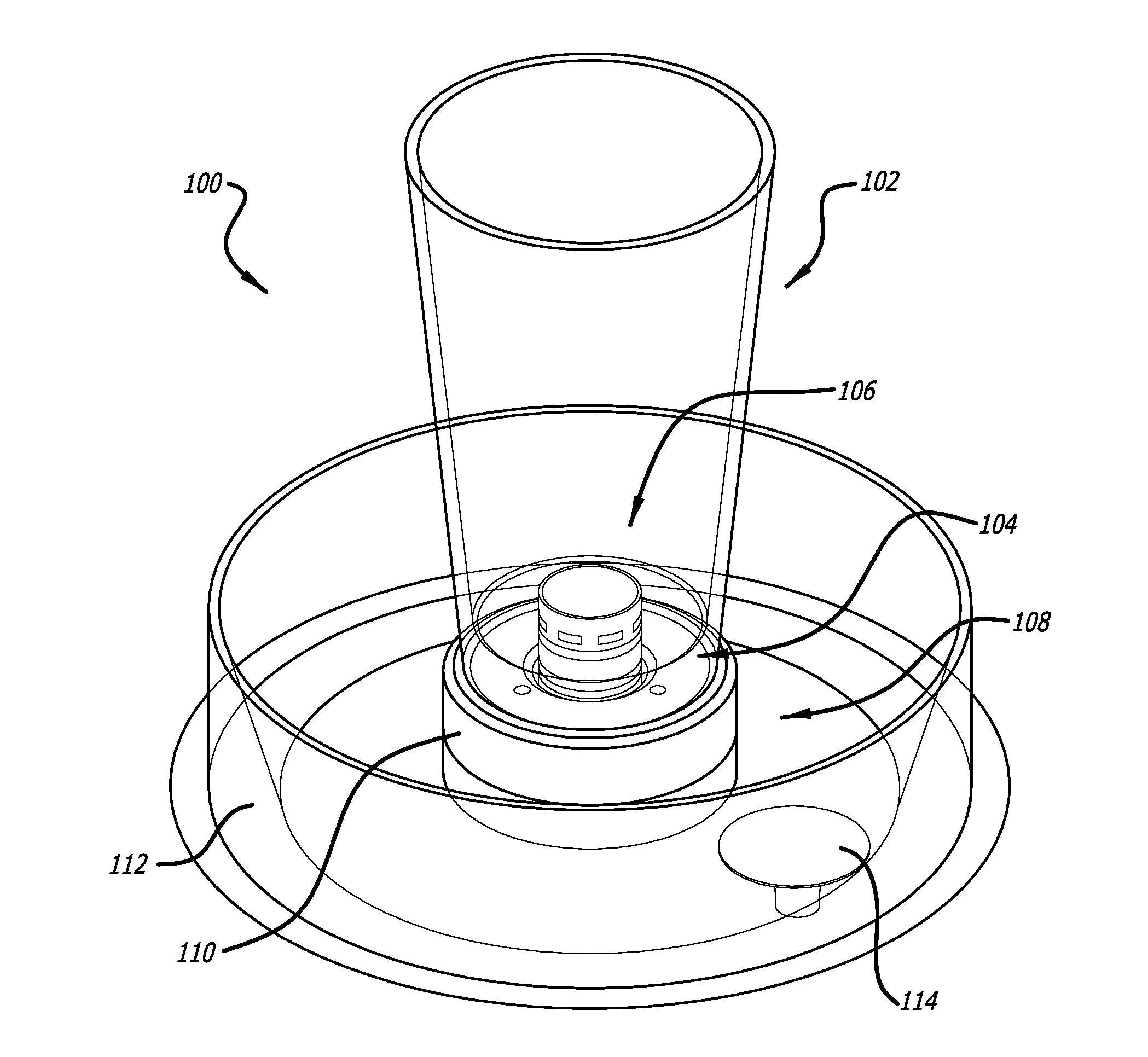
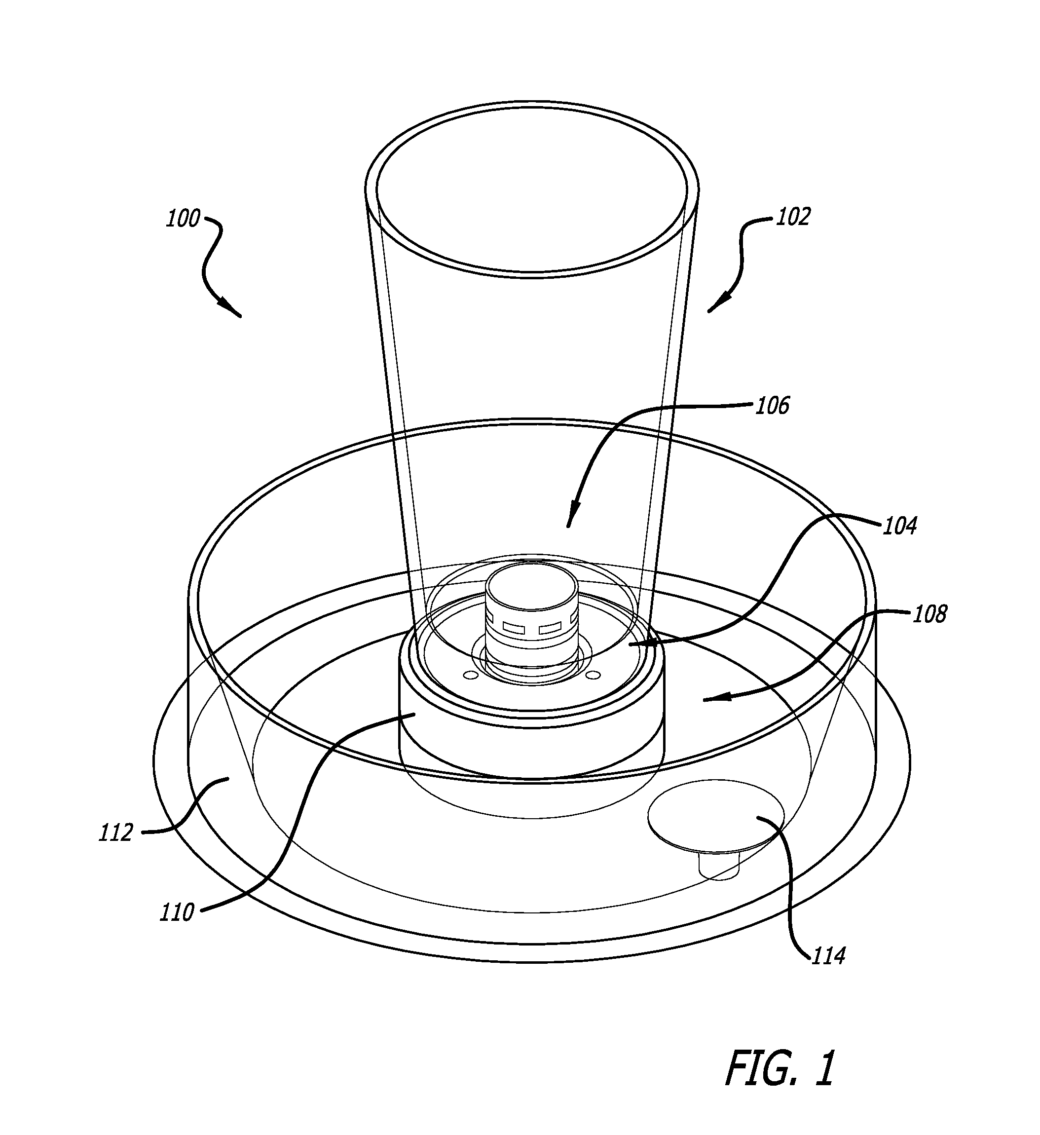
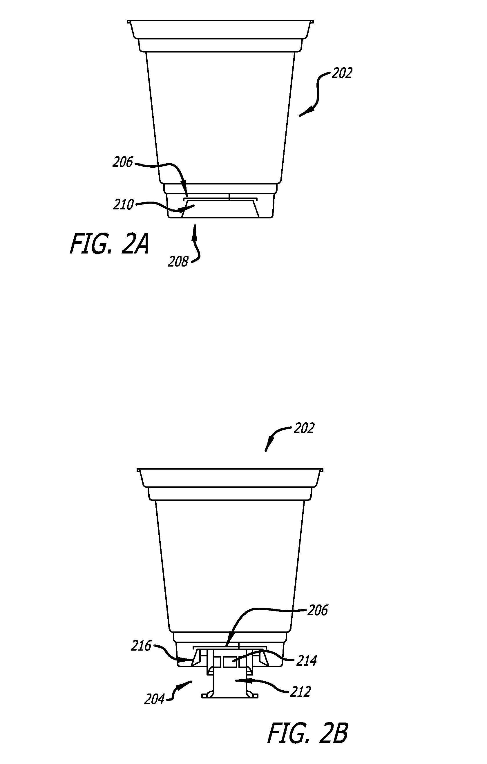
[0058]In the following description of exemplary embodiments, reference is made to the accompanying drawings that form a part hereof, and in which it is shown by way of illustration specific embodiments in which the invention can be practiced. It is to be understood that other embodiments can be used and structural changes can be made without departing from the scope of the embodiments of this invention. As used herein, the terms “couple,”“connect,” and “attach” are interchangeable and include various forms of connecting one part to another either directly or indirectly. Also, it should be appreciated that one or more structural features described in one embodiment could be implemented in a different embodiment, even if not specifically mentioned as being a feature thereof.

[0059]In the following description, numerous specific details are set forth, such as examples of specific containers and liquids, in order to provide a thorough understanding of the present invention. It will be ap...


PUM

PropertyMeasurementUnit
angleaaaaaaaaaa
angleaaaaaaaaaa
angleaaaaaaaaaa

Abstract

A fluid dispensing system and assembly, including a connection or coupling device, a valve, a housing, a user interface, a filling device, and a fitting to couple to a fluid source. The connection or coupling device may include a magnetic ring crimped to the bottom of a container, and methods of manufacture are described. The valve may include a first sensor detecting proper placement of the fluid container based on a magnetic material positioned at the bottom of the fluid container, a plunger having a plunger shaft coupled thereto, the plunger selectively placing the valve in fluid communication with the fluid container, and a solenoid coupled to the plunger shaft and moving the plunger shaft to transition the plunger between an open position and a closed position. The user interface may be coupled to the valve to enable selection of at least a fluid container size and a dispensing mode.

Description

PRIORITY[0001]This application claims priority to U.S. Provisional Application No. 61 / 582,036, filed Dec. 30, 2011, and is a continuation-in-part of U.S. patent application Ser. No. 13 / 008,786, filed Jan. 18, 2011, which claims priority to U.S. Provisional Application No. 61 / 296,305, filed Jan. 19, 2010, and is a continuation-in-part of U.S. patent application Ser. No. 12 / 992,881, which was filed as a U.S. national stage application under 35 U.S.C. §371 of International Application No. PCT / US2009 / 044534, filed May 19, 2009, which claims priority to U.S. Provisional Application No. 61 / 054,686, filed May 20, 2008, and to U.S. Provisional Application No. 61 / 154,726, filed Feb. 23, 2009. Each of the aforementioned applications is incorporated by reference in its entirety into this application.BACKGROUND[0002]Various types of containers are designed to hold beverages, from cans and bottles, to cardboard boxes and wooden casks. Liquid may be stored in large containers and transferred to r...

Claims


Application Information

Patent Timeline
Patent Type & Authority Applications(United States)
IPC IPC(8): B67C3/26A47G19/22B65D1/06
CPCB67C3/264A47G19/2255B65D1/06A47G19/2205B67D1/0081F16K27/07B67D2210/00065B67D1/0894B67D1/1275B67B1/10B65D41/02
Inventor SPRINGER, JOSHUA
Owner GRINON INDS
Why Eureka
Try Eureka