Methods For Geosteering A Drill Bit In Real Time Using Drilling Acoustic Signals

a geosteering and drill bit technology, applied in the direction of surveying, directional drilling, borehole/well accessories, etc., can solve the problems of acoustic signals, normally derived geometry and distribution information of pay zones before drilling, and a significant error

Active Publication Date: 2013-05-16
SAUDI ARABIAN OIL CO
View PDF2 Cites 24 Cited by
  • Summary
  • Abstract
  • Description
  • Claims
  • Application Information

AI Technical Summary

Benefits of technology

[0017]Embodiments of the invention are directed to an apparatus, computer program product, and method for steering a drill bit through a vertical and lateral pay zone in real-time for well production in the oil and gas industry. In particular, in accordance with an embodiment of the invention, there is provided an apparatus for steering a drill bit within a pay zone in a lateral well. The apparatus includes a drill bit configured to drill through an encountered rock in the lateral well, and a sensor arranged adjacent to the drill bit and configured to receive real-time acoustic signature data indicating acoustic signatures of the rock being encountered by the drill bit. The apparatus further includes a processor configured to compare the received real-time acoustic signature data indicating acoustic signatures of the rock being encountered by the drill bit to predetermined acoustic signatures determined for a plurality of rock samples. The processor is further configured to identify a lithology type of the rock being encountered by the drill bit based on the comparison, and steer the drill bit in a predefined direction, in real-time, based on the identified lithology type of the rock, for maintaining the drill bit within the pay zone of the lateral well.
[0018]In accordance with another embodiment of the invention, there is provided a method for steering a drill bit within a pay zone in a lateral well. The method includes receiving acoustic signature data from a downhole processor assembly. The acoustic signature data includes an amplitude spectrum and one or more acoustic characteristics evaluated from an acoustic signal provided by a sensor arranged adjacent to a drill bit and generated in real-time as a result of rotational contact of the drill bit with encountered rock in the lateral well during drilling. The method further includes comparing the received real-time acoustic signature data to predetermined acoustic signatures determined for a plurality of rock samples, and identifying a lithology type of the rock being encountered by the drill bit based on the comparison. Further, the method includes steering the drill bit in a predefined direction, in real-time, based on the identified lithology type of the rock, for maintaining the drill bit within the pay zone of the lateral well.
[0019]In accordance with another embodiment of the invention, there is provided a computer program product embodied on a computer readable storage medium. The computer program product is configured to control a processor to perform a process. The process includes receiving acoustic signature data from a downhole processor assembly. The acoustic signature data includes an amplitude spectrum and one or more acoustic characteristics evaluated from an acoustic signal provided by a sensor arranged adjacent to a drill bit and generated in real-time as a result of rotational contact of the drill bit with encountered rock in the lateral well during drilling. The process further includes comparing the received real-time acoustic signature data to predetermined acoustic signatures determined for a plurality of rock samples, and identifying a lithology type of the rock being encountered by the drill bit based on the comparison. Further, the process includes steering the drill bit in a predefined direction, in real-time, based on the identified lithology type of the rock, for maintaining the drill bit within the pay zone of the lateral well.

Problems solved by technology

However, this is rarely the case.
Geometry and distribution information of a pay zone before drilling, normally derived from seismic survey, offset wells, and local geological information, has significant error.
Therefore, it can be extremely difficult to achieve good contact (i.e., high portion of a lateral section within a pay zone) if only the predefined geometry and distribution information of the pay zone is used to steer the drill bit through the pay zone in the lateral well, especially when the pay zone is thin.
The acoustic telemetry methodology, albeit arguably the cheapest to implement, has a limited data rate, and thus, cannot support the transmission of raw data, requiring some form of lossy data reduction.
Therefore, these tools are not real-time tools.
Therefore, the aforementioned conventional geosteering systems are limited in that the formation used to steer the drill bit is derived at the location of the measurement sensor a few dozen feet behind the drill bit.
When this happens, it may require a significant distance to adjust the drill bit back into the pay zone, resulting in a lateral section of the well with some non-productive fractions and thus reducing productivity of hydrocarbon production.
As previously described, conventional geosteering systems are also limited by the use of resistivity techniques producing non-unique solutions, thereby reducing productivity of hydrocarbon production.
Although providing data in a reduced form requiring only a bit rate speed, these conventional geosteering systems fail to provide raw data real-time which can be used for further analysis.
It is nearly impossible to construct additional interpretation models or modify any interpretation models generated by this type of downhole processor.
Further, they require additional and potentially expensive hardware that must be positioned between the drill bit and the drill.

Method used


Image

  • Methods For Geosteering A Drill Bit In Real Time Using Drilling Acoustic Signals
  • Methods For Geosteering A Drill Bit In Real Time Using Drilling Acoustic Signals
  • Methods For Geosteering A Drill Bit In Real Time Using Drilling Acoustic Signals

Examples


Embodiment Construction

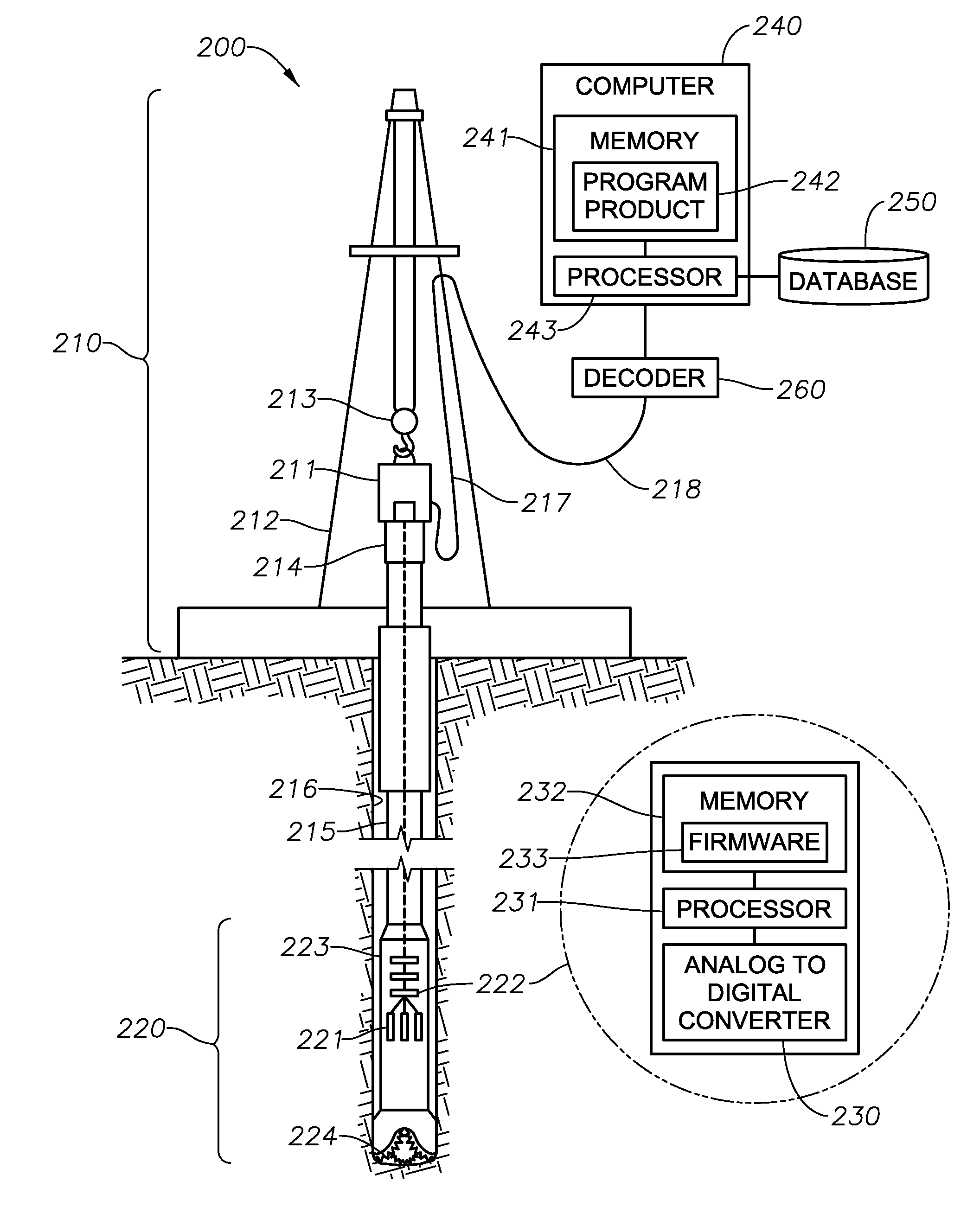
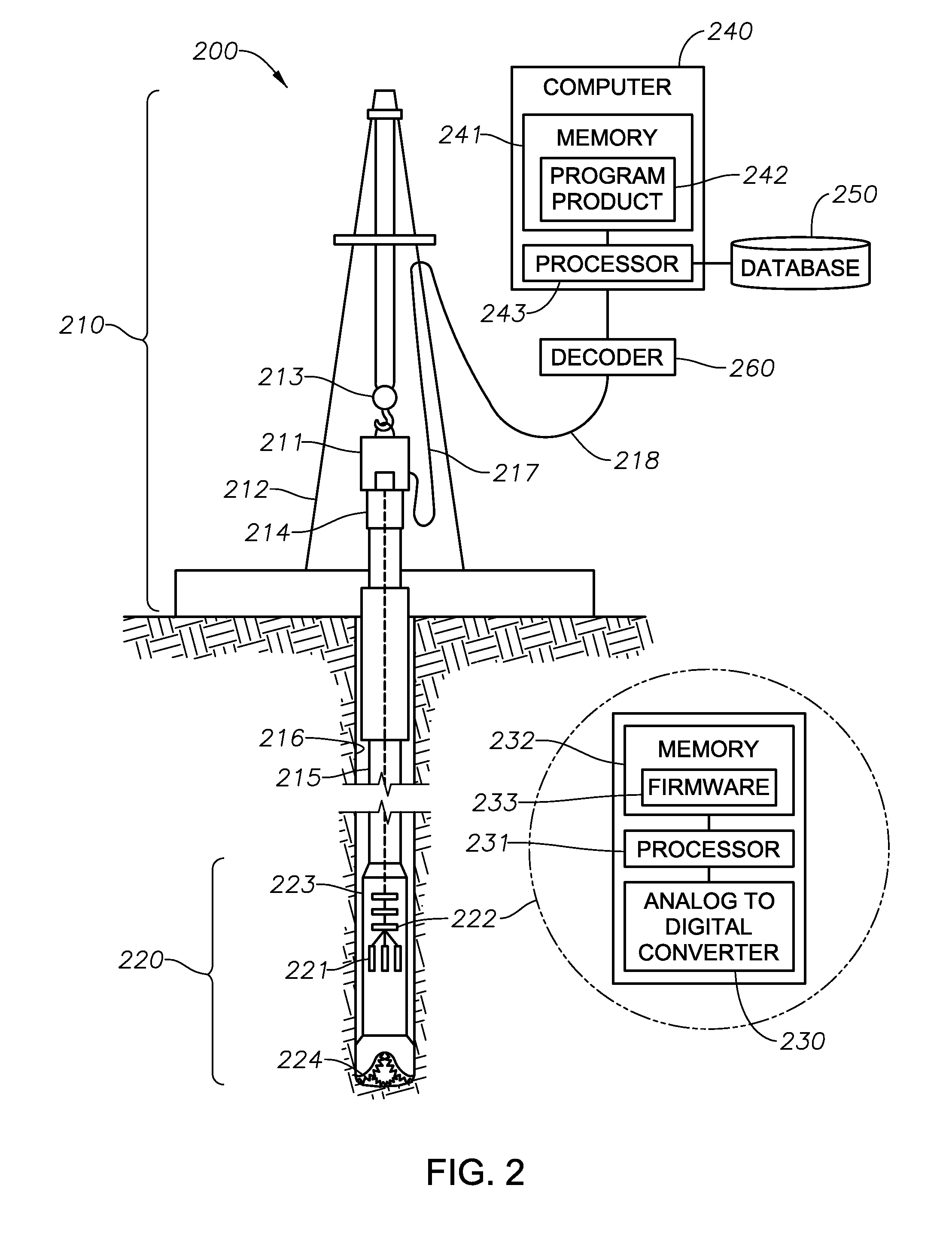
[0031]The present invention will now be described more fully hereinafter with reference to the accompanying drawings, which illustrate embodiments of the invention. This invention may, however, be embodied in many different forms and should not be construed as limited to the illustrated embodiments set forth herein. Rather, these embodiments are provided so that this disclosure will be thorough and complete, and will fully convey the scope of the invention to those skilled in the art. Like numbers refer to like elements throughout. Prime notation, if used, indicates similar elements in alternative embodiments.

[0032]Generally, embodiments of the invention are directed to drill bit acoustic logging tools for vertically and laterally steering a drill bit. In particular, the tools employed use drill bit sounds (i.e., hereinafter referred to as “drilling acoustic signals”) generated by the drill bit drilling into rock to derive acoustic properties, lithology or rock types, and rock physi...


PUM


Abstract

Disclosed is an apparatus, method, and program product for steering a drill bit within a pay zone in a lateral well. The method includes receiving acoustic signature data from a downhole processor assembly. The acoustic signature data includes an amplitude spectrum and one or more acoustic characteristics evaluated from an acoustic signal provided by a sensor arranged adjacent to a drill bit and generated in real-time as a result of rotational contact of the drill bit with encountered rock in the lateral well during drilling. The method further includes comparing the received real-time acoustic signature data to predetermined acoustic signatures determined for a plurality of rock samples, and identifying a lithology type of the rock being encountered by the drill bit based on the comparison. Further, the method includes steering the drill bit in a predefined direction, in real-time, based on the identified lithology type of the rock, for maintaining the drill bit within the pay zone of the lateral well.

Description

RELATED APPLICATIONS[0001]This application is related to, and claims priority to, U.S. Provisional Patent Application No. 61 / 559,769, tiled on Nov. 15, 2011, and U.S. Provisional Patent Application No. 61 / 694,576, filed on Aug. 29, 2012, the disclosures of which are incorporated herein by reference in their entirety.BACKGROUND[0002]1. Field of the Invention[0003]Embodiments of the invention generally relate to hydrocarbon production, and more particularly, to drilling operations using well logging and measurement techniques for steering a drill bit within a pay zone in a lateral well using acoustic signals generated by the drill bit drilling into rock.[0004]2. Description of the Related Art[0005]To increase oil or gas production of a well, an effective approach is to drill the well with a substantially lateral trajectory (e.g., a horizontal or lateral well) in a petroleum reservoir to increase the drainage area in the reservoir. It is therefore desired to maintain the drill bit with...

Claims


Application Information

Patent Timeline
Patent Type & Authority Applications(United States)
IPC IPC(8): E21B44/00E21B7/06
CPCE21B7/06E21B44/00E21B7/04G01V1/50E21B47/091E21B44/02E21B47/095E21B47/026
Inventor YANG, YUNLAI
Owner SAUDI ARABIAN OIL CO
Why Eureka
Try Eureka