Voice coil motor

Active Publication Date: 2013-05-16
LG INNOTEK CO LTD
View PDF15 Cites 67 Cited by
  • Summary
  • Abstract
  • Description
  • Claims
  • Application Information

AI Technical Summary

Benefits of technology

[0011]The VCM according to the present disclosure has an advantageous effect in that a signal line of a flexible circuit board for tiling an image sensor along with a rotor is dispersively arranged to inhibit an area of the flexib

Problems solved by technology

However, the conventional camera module suffers from disadvantages of disablement of auto focus function to adjust a gap between a le

Method used


Image

  • Voice coil motor
  • Voice coil motor
  • Voice coil motor

Examples


first exemplary embodiment

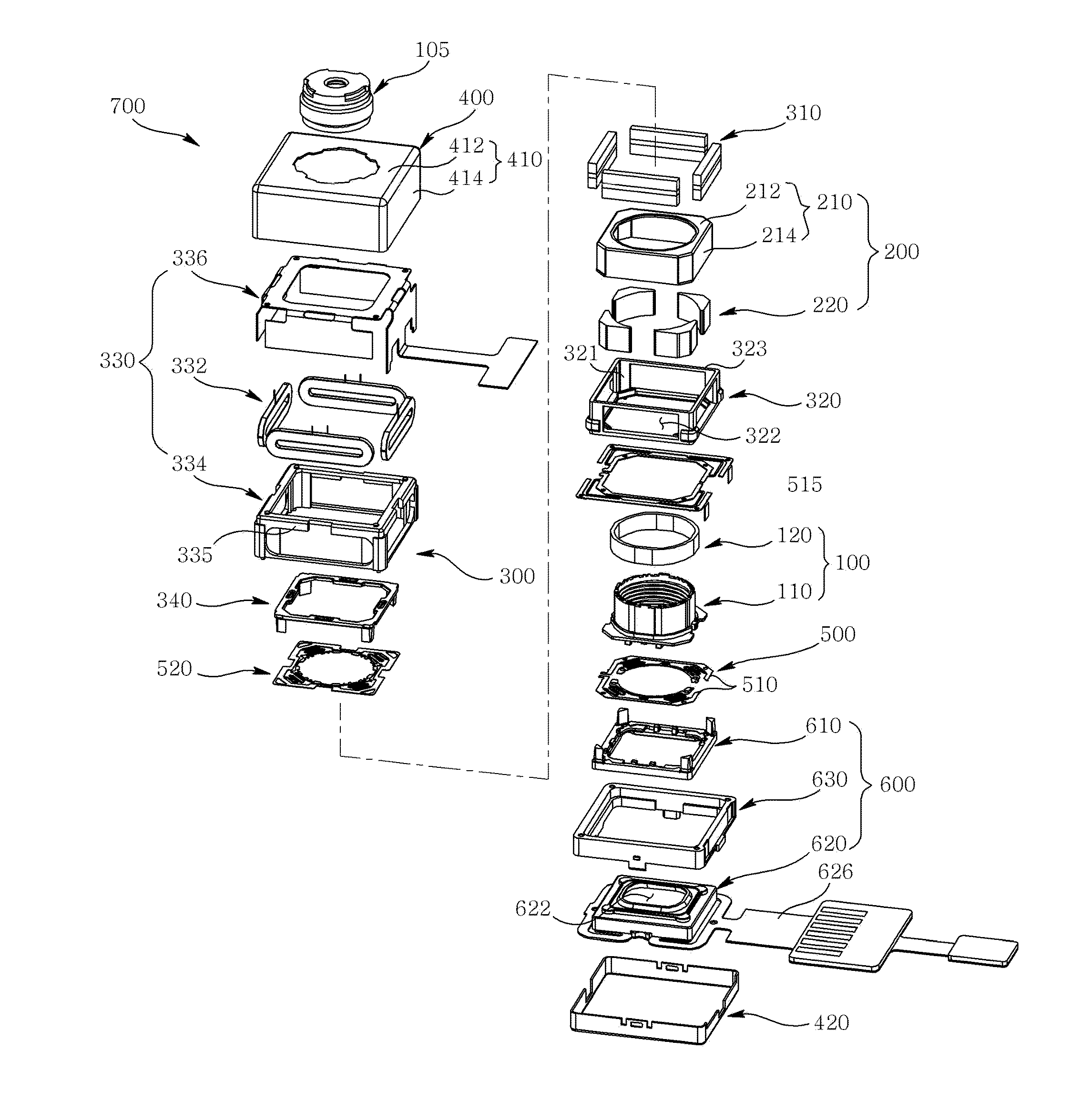
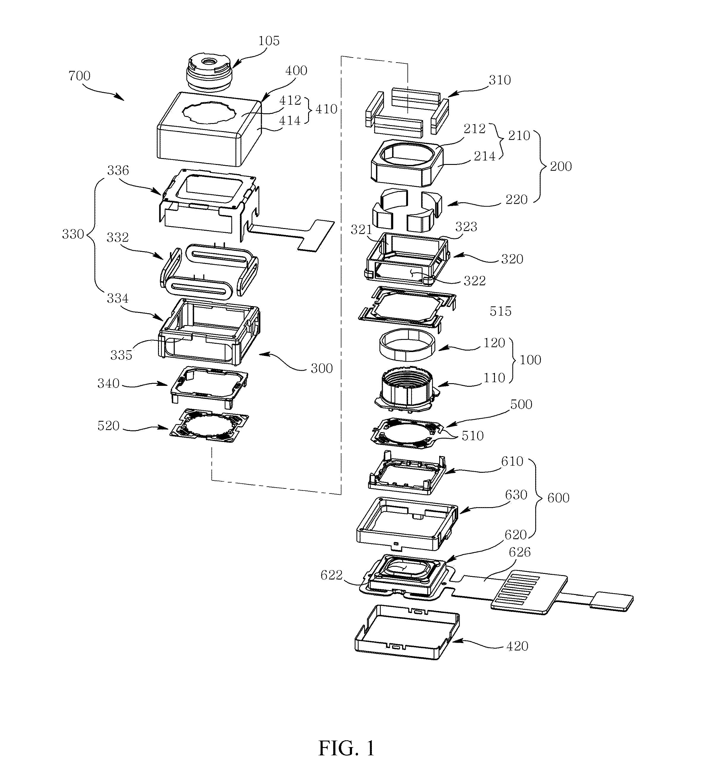
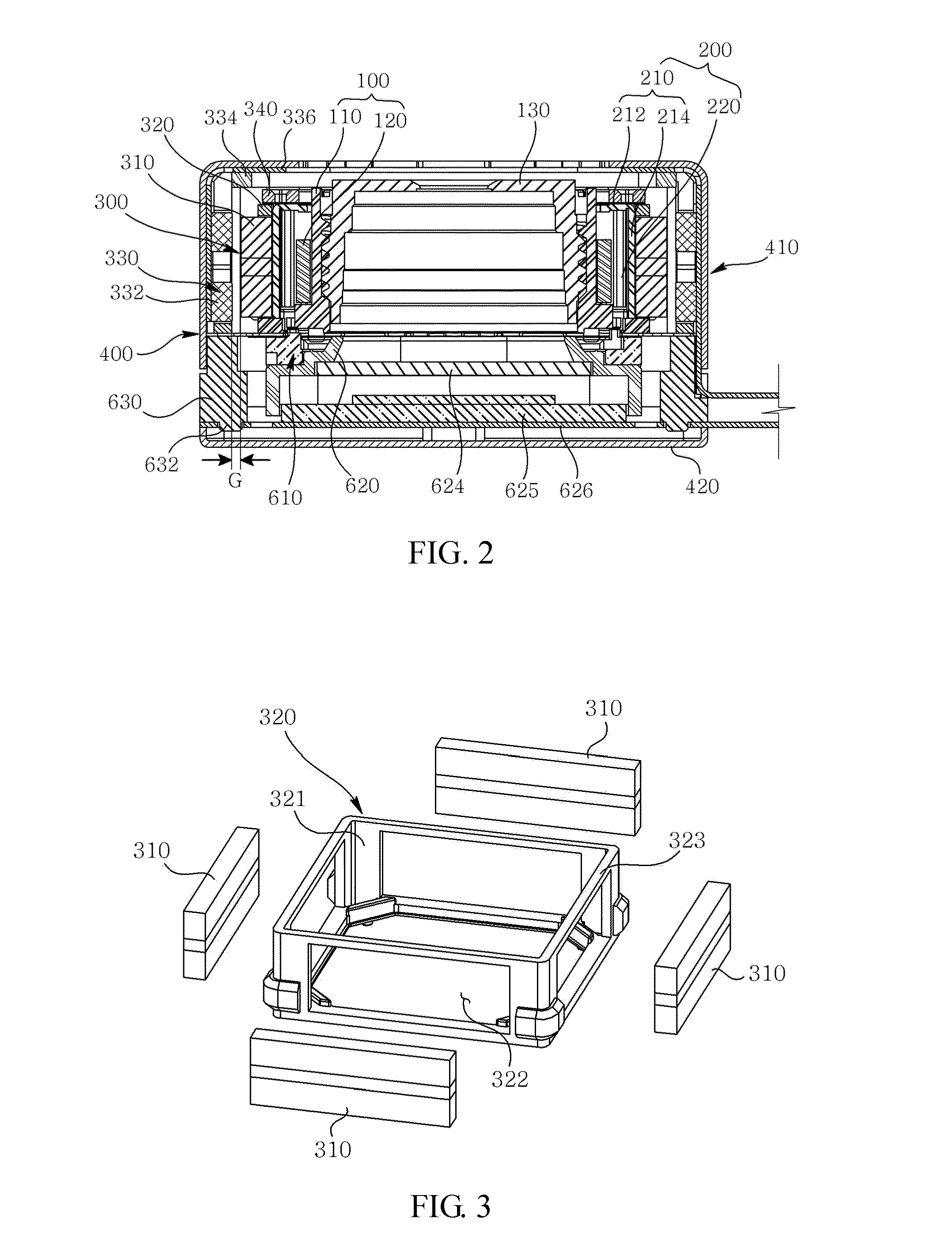
[0035]FIG. 1 is an exploded perspective view illustrating a VCM according to a first exemplary embodiment of the present disclosure, FIG. 2 is an assembled cross-sectional view of FIG. 1, and FIG. 3 is an extracted perspective view illustrating a housing and a tilt magnet of FIG. 1.

[0036]Referring to FIGS. 1, 2 and 3, a voice coil motor (hereinafter referred to as VCM, 700) may include a rotor (100), a stator (200), a tilt unit (300) and a cover can (400). In addition, the VCM (700) may further include an elastic member (500) and a base unit (600).

[0037]The rotor (100) is mounted with a lens (105), and serves to perform an auto focusing function by vertically moving relative to an upper surface (horizontal plane) of the base unit (600) arranged at a rear side with an image sensor. Furthermore, the rotor (100) performs a handshake correction function by tiling to four (4) directions relative to the upper surface (horizontal plane) of the base unit (600) in response to the tilt unit (...

second exemplary embodiment

[0061]FIG. 4 is an exploded perspective view illustrating a VCM according to a second exemplary embodiment of the present disclosure, FIG. 5 is an assembled cross-sectional view of FIG. 4, FIG. 6 is an extracted perspective view illustrating a housing and a tilt magnet of FIG. 4, and FIG. 7 is an extracted perspective view illustrating a tilt coil driving unit of FIG. 4.

[0062]Referring to FIGS. 4 to 7, a voice coil motor (hereinafter referred to as VCM, 700) may include a rotor (100), a stator (200), a tilt unit (300), a rigid circuit board (700) and a flexible circuit board (800). In addition, the VCM (700) may further include a cover can (400), elastic members (500) and a base unit (600).

[0063]The rotor (100) is mounted with a lens (105), and serves to perform an auto focusing function by vertically moving relative to an upper surface of the base unit (600) arranged at a rear side with an image sensor. Furthermore, the rotor (100) performs a handshake correction function by horizo...

third exemplary embodiment

[0108]FIG. 8 is an exploded perspective view illustrating a VCM according to a third exemplary embodiment of the present disclosure, FIG. 9 is an assembled cross-sectional view of FIG. 8, FIG. 10 is an extracted perspective view illustrating a housing and a tilt magnet of FIG. 8, FIG. 11 is a perspective view illustrating a flexible circuit board mounted with a rigid circuit board of FIG. 8, FIG. 12 is a perspective view illustrating a state of a second board unit of a flexible circuit board that is not bent, and FIG. 13 is a perspective view illustrating a state of a second board unit of a flexible circuit board of FIG. 12 that is bent.

[0109]Referring to FIGS. 8 to 13, a voice coil motor (hereinafter referred to as VCM, 900) may include a rotor (100), a stator (200), a tilt unit (300), a rigid circuit board (700) and a flexible circuit board (800). In addition, the VCM (900) may further include a cover can (400), elastic members (500) and a base unit (600).

[0110]The rotor (100) is ...


PUM


Abstract

A VCM is disclosed, the VCM including a rotor including a bobbin arranged at an upper surface of a base formed with an opening, and a driving coil wound on the bobbin, a stator including a driving magnet opposite to the driving coil, and a yoke secured by the driving magnet at an inner surface of a lateral plate, and a tilting unit including a tilt magnet arranged at an outer surface of the lateral plate, a housing fixing the tilt magnet, and a tilt coil unit opposite to the tilt magnet.

Description

CROSS-REFERENCE TO RELATED APPLICATIONS[0001]This application claims the benefit under 35 U.S.C. §119 of Korean Patent Application Nos. 10-2011-0119351, filed Nov. 16, 2011, 10-2011-0141199, filed Dec. 23, 2011, 10-2011-0141200, filed Dec. 23, 2011, and 10-2011-0141201, filed Dec. 23, 2011, which are hereby incorporated by reference in their entirety.BACKGROUND[0002]1. Field of the invention[0003]The present disclosure relates to a VCM (Voice Coil Motor).[0004]2. Description of Related Art[0005]Recently, a mobile phone mounted with a camera module storing an object as a digital image or a video, a smart phone and a smart pad of a type of a portable personal computer.[0006]A conventional camera module includes a lens and an image sensor module converting light having passed the lens to a digital image. However, the conventional camera module suffers from disadvantages of disablement of auto focus function to adjust a gap between a lens and an image sensor, and lack of function to cor...

Claims


Application Information

Patent Timeline
IPC IPC(8): H02K41/035
CPCH02K41/035G02B7/102H02K2201/18H02K16/00H02K41/0354G02B7/105H02K33/16H02K35/04H02K35/00H02K33/00H02K33/02G02B7/08G02B27/646
Inventor HAN, JIN SUK
Owner LG INNOTEK CO LTD
Why Eureka
Try Eureka