Linear vibration device

a vibration device and linear technology, applied in mechanical vibration separation, dynamo-electric machines, electrical apparatus, etc., can solve the problems of affecting the use of various vibration modes, limiting the lift of the vibration motor, and disturbing other people around the user of the mobile phone. , to achieve the effect of stable operation, enhancing productivity and durability, and stably realizing

Inactive Publication Date: 2013-05-16
YOUNG JIN HITECH
View PDF2 Cites 19 Cited by
  • Summary
  • Abstract
  • Description
  • Claims
  • Application Information

AI Technical Summary

Benefits of technology

[0013]The upward and downward movement of the vibrating body is limited by magnetic forces of the yoke and the upper and lower plates, making it possible to secure a stable operation. A gap can be secured so as not to cause a contact on the upper and lower sides, so only one gap may be managed between the coil and the magnet, making it possible to enhance productivity and durability.
[0014]As discussed above, the linear vibration device of the present invention does not employ a brush or a rec

Problems solved by technology

In general, mobile phones widely use bells or melodies to inform of the termination of calls, but the noise generated due to the bells or melodies may disturb other persons around the user of the mobile phone.
However, the brush limits a lift of the vibration motor, and fixes a limit in the use of various vibration modes.
Moreover, a vibration motor having a quick response is required in a touch type mobile phon

Method used


Image

  • Linear vibration device
  • Linear vibration device
  • Linear vibration device

Examples


Embodiment Construction

[0025]Hereinafter, exemplary embodiments of the present invention will be described in detail with reference to the accompanying drawings.

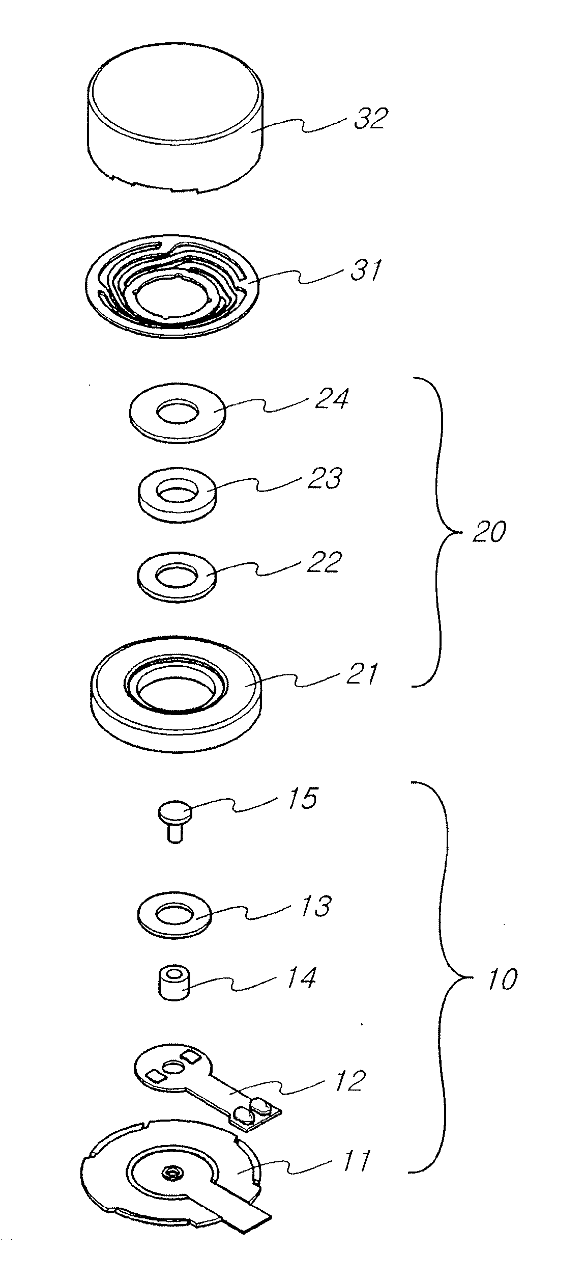
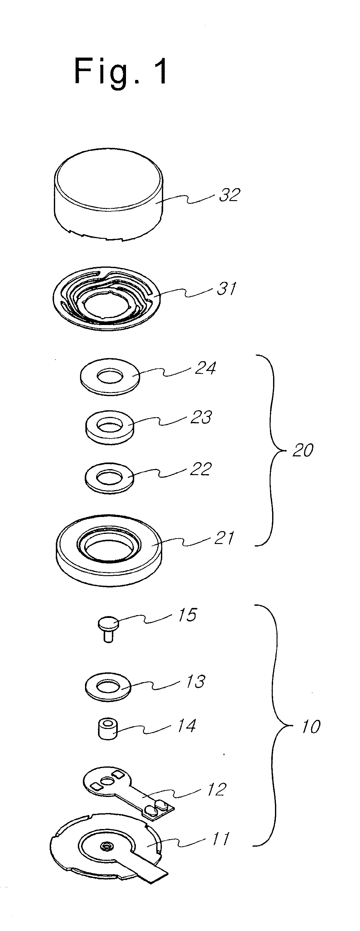
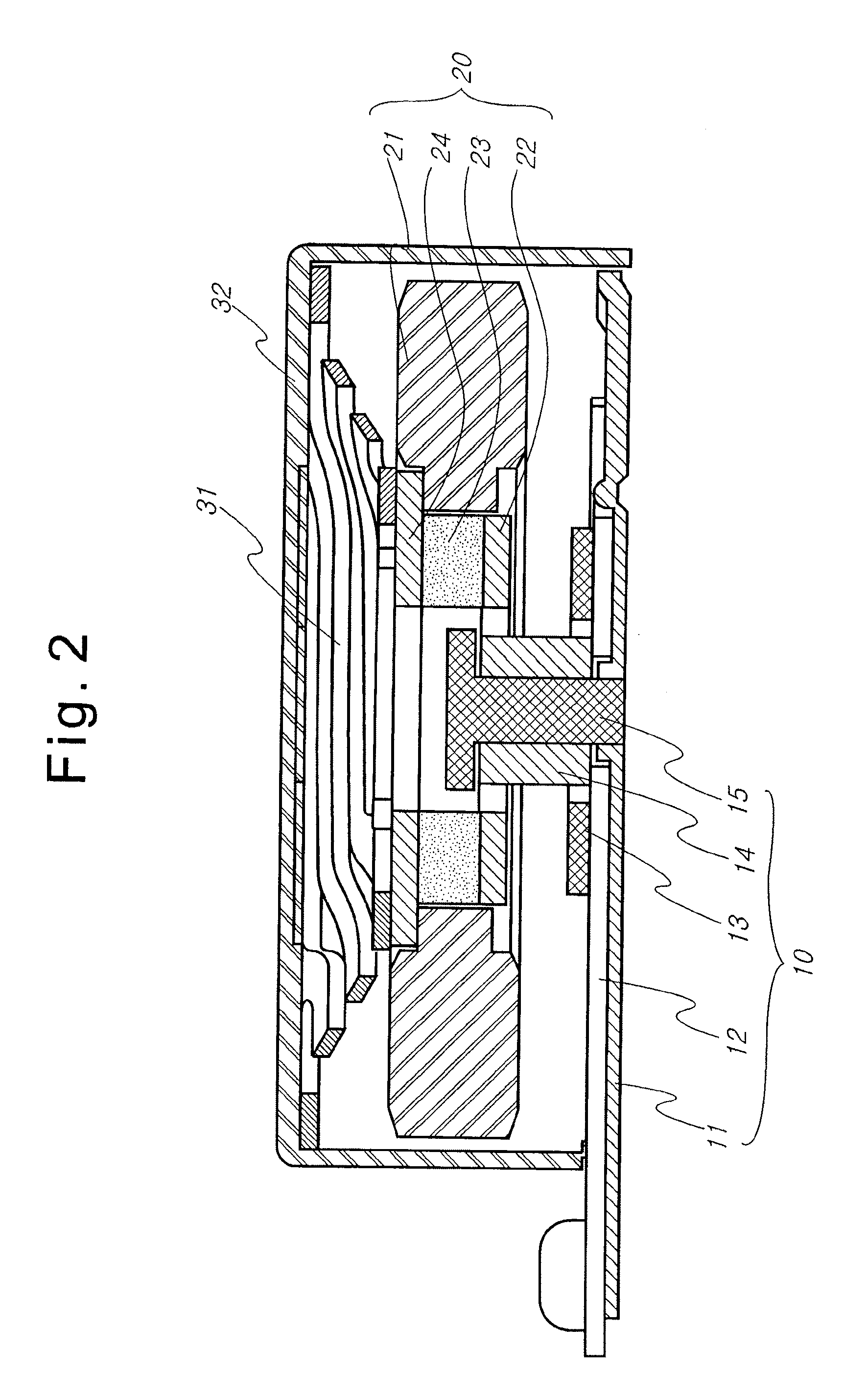
[0026]As illustrated in FIG. 1, a linear vibration motor according to the present invention includes a vibrating body 20 having a magnet 23 creating a permanent magnetic field, lower and upper plates 22 and 24 installed to concentrate a direction of a magnetic force of the magnet 23 to a specific direction respectively, and a vibrator 21 coupled to the upper plate 24 and configured to increase a magnitude of vibrations, the vibrating body 20 being finally assembled with the vibrator 21.

[0027]In this case, the vibrator 21 assembled in the vibrating body 20 preferably has a density generally heavier than that of iron. The linear vibrator motor includes a resilient body 31 coupled to an upper surface of the upper plate 24 to effectively transfer a vibration sound of the vibrating body 20 to the outside and configured to help the vibrating body 20 mov...


PUM


Abstract

The present invention provides a linear vibration device in which a PCB is coupled to a bracket having an extension piece protruding at a peripheral portion thereof to transfer an external electrical signal to a coil and a yoke of a stator is installed on an upper surface of the PCB to be coupled to the coil, in order to maximally generate an electromagnetic force in one direction. In addition, an upper plate and a lower plate are configured to concentrate a magnetic field of a magnet configured to create a magnetic field corresponding to an electromagnetic force of the yoke formed by the coil to one direction. Accordingly, a vibrating body includes a vibrator which is operated upward and downward in response to an electromagnetic force concentrated by the yoke, increasing vibration feelings due to the upward and downward movement thereof.

Description

BACKGROUND OF THE INVENTION[0001]1. Field of the Invention[0002]The present invention relates to a linear vibration device, and more particularly to a linear vibration device adapted to generate vibrations in electronic devices such as a mobile phone when a vibrating body having a weight body is moved upward and downward according to an input electrical signal with a specific frequency, while varying vibrations.[0003]2. Description of the Prior Art[0004]In general, mobile phones widely use bells or melodies to inform of the termination of calls, but the noise generated due to the bells or melodies may disturb other persons around the user of the mobile phone. In order to solve this problem, vibration motors are designed to inform the termination of calls not with a sound but with vibrations. In such a vibration motor, a vibrating body is generally mounted to a typical DC motor employing a brush. However, the brush limits a lift of the vibration motor, and fixes a limit in the use of...

Claims


Application Information

Patent Timeline
IPC IPC(8): H02K33/00
CPCH02K33/16B06B1/045
Inventor YU, JIN HAN
Owner YOUNG JIN HITECH
Why Eureka
Try Eureka