Wide Input Voltage Range Power Supply Circuit

a power supply circuit and input voltage range technology, applied in the field of power supply circuits, can solve the problems of large number of catalog numbers and associated relays that need to be manufactured and warehoused, increase size, cost, heat generation, etc., and achieve the effect of lowering the input voltag

Active Publication Date: 2013-05-16
ROCKWELL AUTOMATION TECH
View PDF9 Cites 34 Cited by
  • Summary
  • Abstract
  • Description
  • Claims
  • Application Information

AI Technical Summary

Benefits of technology

[0008]The present embodiments overcomes the aforementioned problems by providing a circuit that can regulate the input signal voltage so that a single relay can be used over a wide input voltage range. A linear regulator may be used to lower the input voltage to a level that can be tolerated by the relay coil. The linear regulator may be coupled to a high voltage detection circuitry designed to shut down the linear regulator when the input voltage exceeds a predetermined level, such as about 120V. In this way, substantial losses incurred dropping high input voltages down to a predetermined coil operating voltage are avoided because the linear regulator is not conducting current while it is shut down. By regulating a wide range of input voltages down to a lower voltage level, a single coil can be used in a wider application range, replacing many catalog numbers with a single catalog number. An under voltage lockout circuit also permits current through the coil only if the input voltage signal exceeds a minimum current threshold.

Problems solved by technology

One difficulty associated with families of electrical devices such as relays is the large number of catalog numbers and associated relays that need to be manufactured and warehoused.
Attempts to accommodate devices to operate on more than one supply voltage results in increased size, cost, and heat generation.
Another difficulty associated with certain relay applications resides in the presence of leakage current from upstream circuitry used to energize the relay coil.
In certain relays, particularly in smaller size relays, such as those mountable on circuit boards and other small support structures, even low levels of leakage current can cause the relay coil to be energized when such energization is not desired, thereby causing the relay to open or close in an undesirable fashion, greatly reducing their reliability.
In either case, the reliability of the relay and the signals produced by the relay can be jeopardized by the leakage current.

Method used


Image

  • Wide Input Voltage Range Power Supply Circuit
  • Wide Input Voltage Range Power Supply Circuit
  • Wide Input Voltage Range Power Supply Circuit

Examples


Embodiment Construction

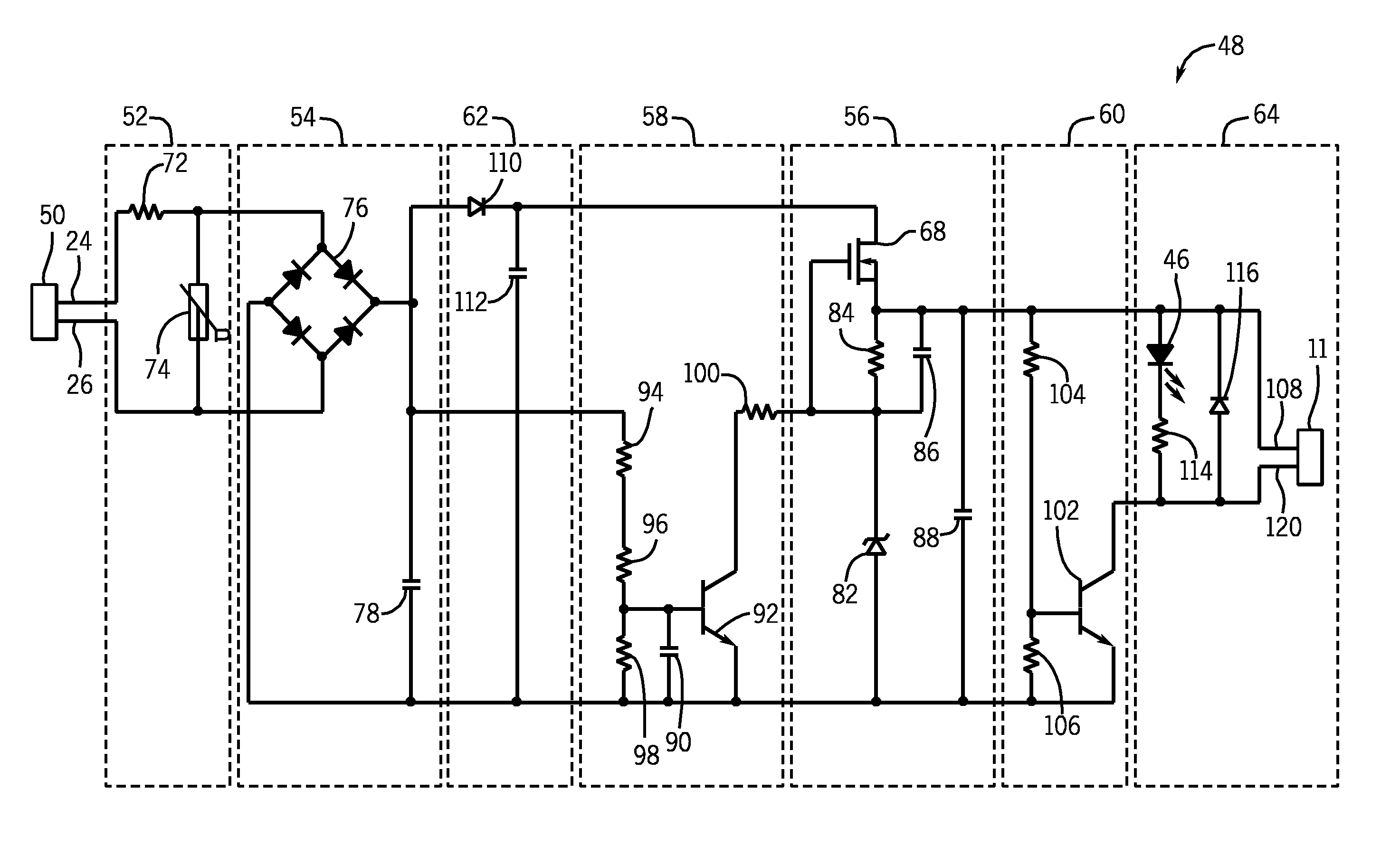
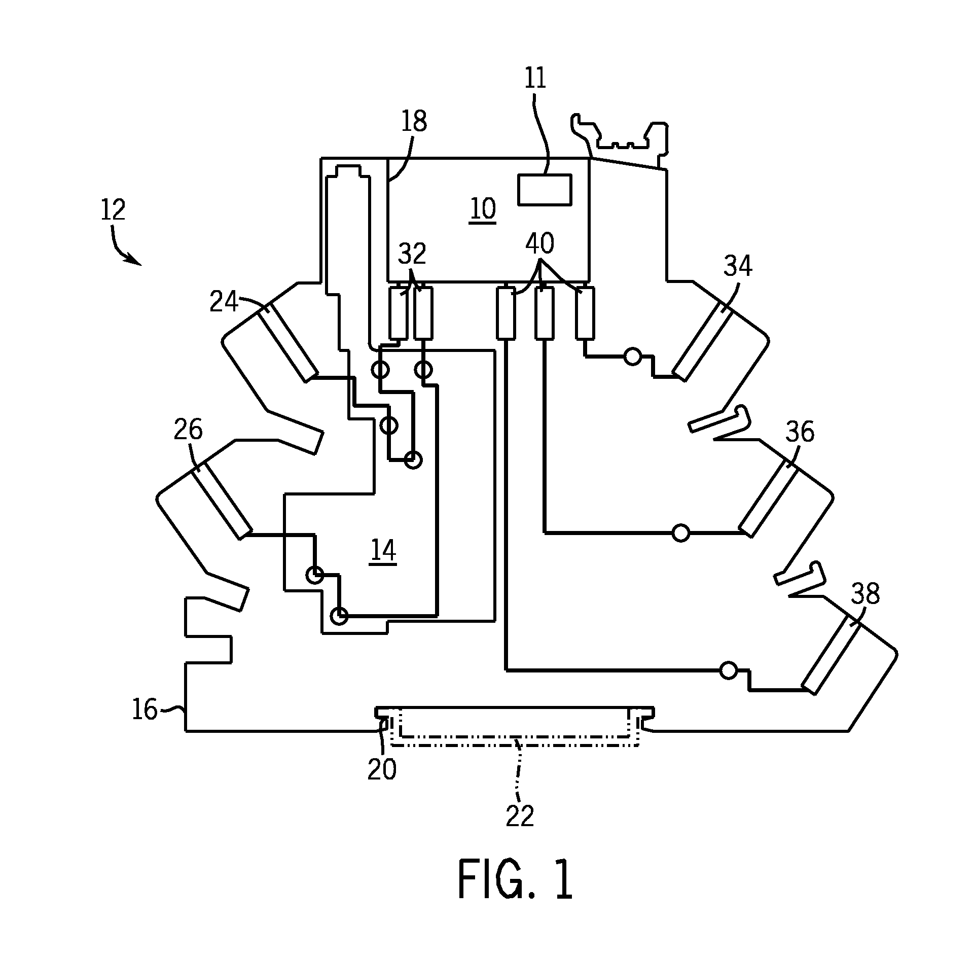
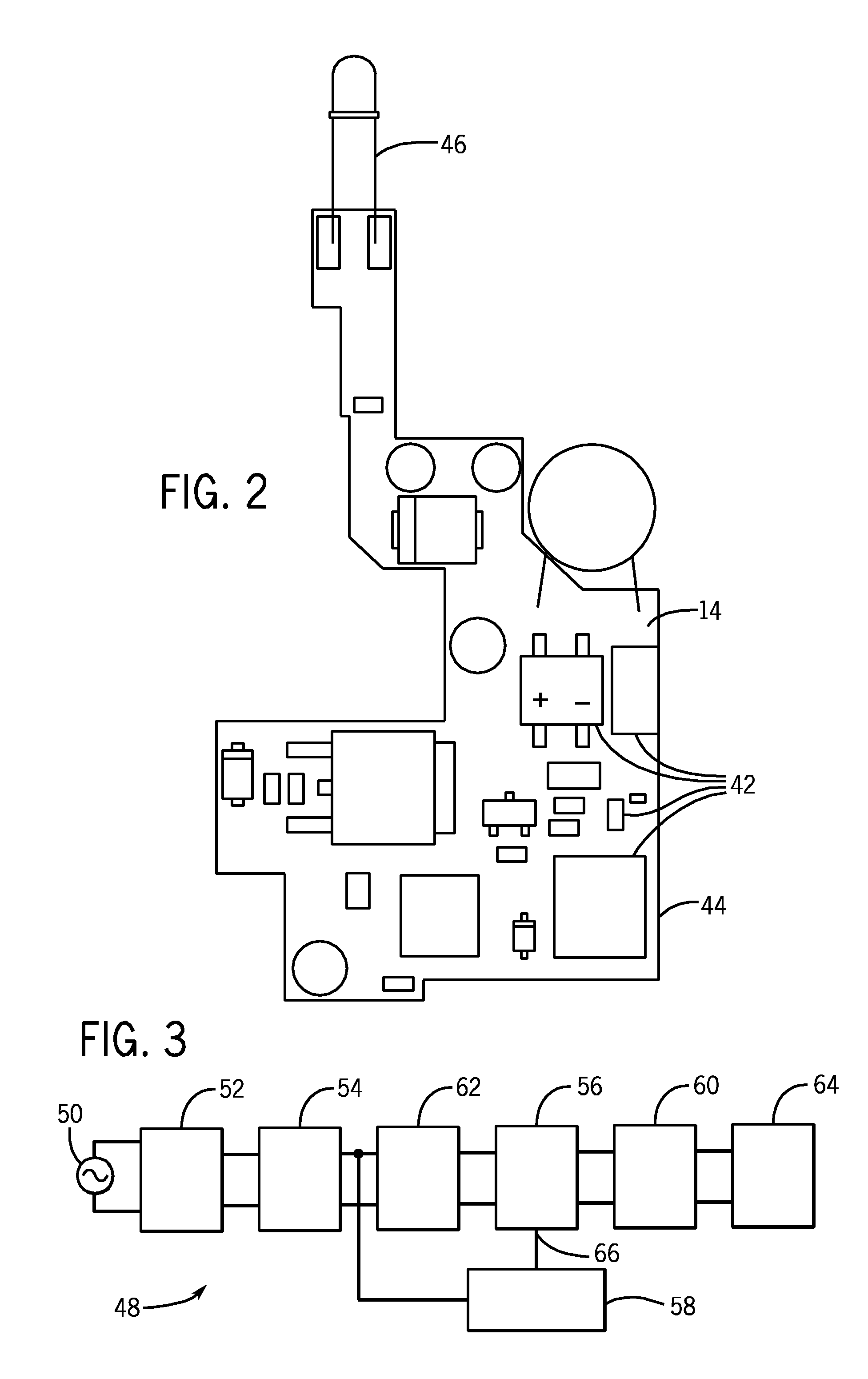
[0017]The following discussion is presented to enable a person skilled in the art to make and use embodiments of the invention. Various modifications to the illustrated embodiments will be readily apparent to those skilled in the art, and the generic principles herein can be applied to other embodiments and applications without departing from embodiments of the invention. Thus, embodiments of the invention are not intended to be limited to embodiments shown, but are to be accorded the widest scope consistent with the principles and features disclosed herein. The following detailed description is to be read with reference to the figures. The figures depict selected embodiments and are not intended to limit the scope of embodiments of the invention. Skilled artisans will recognize the examples provided herein have many useful alternatives and fall within the scope of embodiments of the invention.

[0018]The following description refers to elements or features being “connected” or “coupl...


PUM


Abstract

A wide input voltage power supply circuit for a load includes a first stage and a second stage. The first stage includes a linear regulator circuit configured to maintain an output voltage at a predetermined output voltage level. The linear regulator includes an input for shutting the linear regulator off when an input voltage exceeds a predetermined shut off threshold. The second stage includes a high voltage detection circuit coupled to the input of the linear regulator. The high voltage detection circuit is configured to detect the level of the input voltage and to shut the linear regulator off when the input voltage exceeds the predetermined shut off threshold. An under voltage lockout circuit may be included, the under voltage lockout circuit configured to set a minimum turn-on voltage for the load.

Description

CROSS-REFERENCE TO RELATED APPLICATIONS[0001]This application is a continuation-in-part of U.S. patent application Ser. No. 13 / 297,494, filed Nov. 16, 2011, and entitled “Wide Voltage Range Power Supply Circuit,” which is hereby incorporated by reference.STATEMENT REGARDING FEDERALLY SPONSORED RESEARCH OR DEVELOPMENT[0002]Not applicable.BACKGROUND OF THE INVENTION[0003]The subject matter disclosed herein relates generally to power supply circuits for a load, and, more particularly, to a power supply circuit that will allow a load, such as a relay, to be operated over a wide input voltage range while providing a minimum current operational threshold.[0004]Many applications exist for switching devices such as relays. In general, such devices typically include one or more contacts which can be opened or closed in response to energization of the relay coil. Both electromechanical and solid state relays are commonly available. Sizes and ratings of such devices vary widely, depending upon...

Claims


Application Information

Patent Timeline
Patent Type & Authority Applications(United States)
IPC IPC(8): G05F5/00
CPCH02M1/10H02M7/2176
Inventor GASPERI, MICHAEL
Owner ROCKWELL AUTOMATION TECH
Why Eureka
Try Eureka