Hybrid projector LED low beam headlamp

a projector and low beam technology, applied in the field of optical systems, to achieve the effect of cost of production

Active Publication Date: 2013-05-16
MAGNA INTERNATIONAL INC
View PDF4 Cites 21 Cited by
  • Summary
  • Abstract
  • Description
  • Claims
  • Application Information

AI Technical Summary

Benefits of technology

[0005]The optical system of the present invention solves the drawbacks of previous designs by using an optical system that collects substantially 100% of the light emitted from the light source and effectively directs it to produce the desired beam pattern. This is achieved by a complex combination of different optical control methods including reflector and lens optics. More specifically, the optics system is a lamp assembly which produces the desired beam pattern by using a reflector, a lens, a retainer lens, and an LED as a light source. The cost of producing the lamp assembly according to the present invention is controlled by a design that reduces the optical part count to three main components that maintain proper alignment between the light source and the reflector, the lens, and the retainer lens.
[0006]The innovative optical system of the present invention collects substantially 100% of the light from the light source while effectively shaping the beam pattern using both cylindrical and revolved reflector elements. The combination of a saddle-shaped lens element and the surface of a revolution eliminates any “dogbone” light pattern shape, and the use of a reflective element forms the foreground of the beam pattern. The present invention has the combination of a prism and culminating lens with a culminating and flat reflective reflector. Another feature of the present invention is the integration of retaining features in a retainer lens and the reflector.

Problems solved by technology

This is achieved by a complex combination of different optical control methods including reflector and lens optics.

Method used


Image

  • Hybrid projector LED low beam headlamp
  • Hybrid projector LED low beam headlamp
  • Hybrid projector LED low beam headlamp

Examples


Embodiment Construction

[0022]The following description of the preferred embodiment(s) is merely exemplary in nature and is in no way intended to limit the invention, its application, or uses.

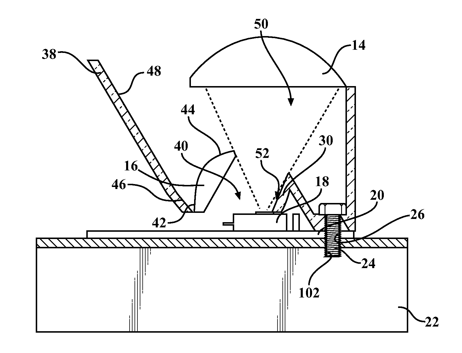
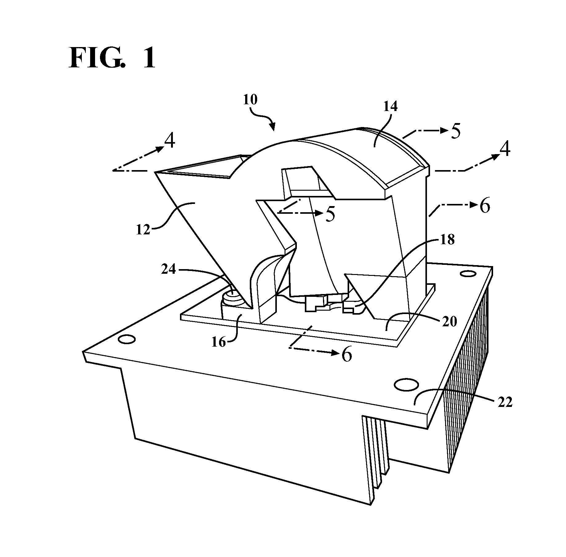
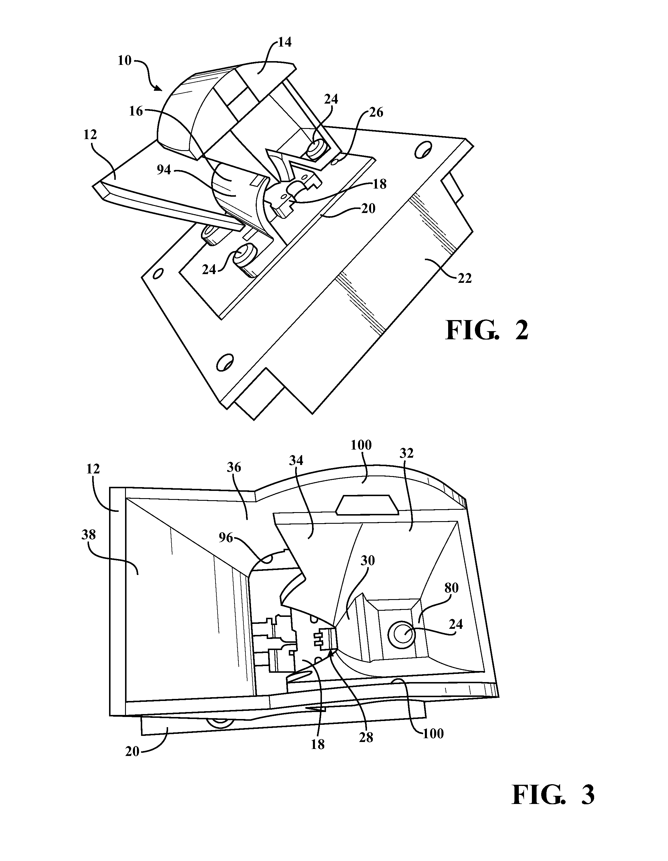
[0023]Referring to the Figures generally, and with specific reference to FIG. 1, a lamp assembly according to the present invention is shown generally at 10. The lamp assembly 10 includes a reflector 12, a lens 14, a retainer lens 16, an LED 18, a printed circuit board (PCB) 20, a heatsink 22, and a plurality of fasteners 24. Referring now to FIG. 2, a perspective view of the lamp assembly 10 is shown with a section of the reflector 12 removed for a better view of the interior of the assembly 10. One of the fasteners 24 in the interior of the reflector 12 is visible, as well as one of a plurality of apertures 26 present in the PCB 20. Some of the apertures 26 are used for providing proper alignment, others are used for receiving one of the fasteners 24, the function of which will be described later.

[0024]Referring now...


PUM


Abstract

The optics system is a lamp assembly which produces the desired beam pattern by using a reflector, a lens, a retainer lens, and an LED as a light source. The lamp assembly has three main components (the reflector, the lens, and the retainer lens) that maintain proper alignment between the light source and the reflector, the lens, and the retainer lens. The optical system collects substantially 100% of the light from the light source while effectively shaping the beam pattern using both cylindrical and revolved reflector elements. The lens has a saddle-shape which is used with the surface of a revolution to eliminate any “dogbone” light pattern shape. The use of a reflective element forms the foreground of the beam pattern.

Description

CROSS-REFERENCE TO RELATED APPLICATIONS[0001]This application claims priority to U.S. Provisional Application No. 61 / 399,968 filed on Jul. 20, 2010. The disclosure of the above application is incorporated herein by reference.FIELD OF THE INVENTION[0002]The present invention relates to an optical system which collects substantially all of the light emitted from a light source to produce a desired beam pattern.BACKGROUND OF THE INVENTION[0003]Current headlamps which incorporate the use of a light emitting diode (LED) use a projector type lens, reflector optics, or closely coupled optics. These types of headlamps suffer from low optical efficiency, high cost, or poor beam pattern distribution.[0004]Accordingly, there exists a need for a headlamp having an LED light source which also includes an optical system that is able to collect substantially all of the light produced by the LED light source, and produce a desired beam pattern efficiently.SUMMARY OF THE INVENTION[0005]The optical s...

Claims


Application Information

Patent Timeline
Patent Type & Authority Applications(United States)
IPC IPC(8): F21V13/04
CPCF21V13/04F21S48/1104F21S48/1154F21S48/1216F21S48/1275F21S48/1323F21S48/137F21S48/1388F21S48/321F21S48/1266F21S41/143F21S41/151F21S41/19F21S41/26F21S41/265F21S41/295F21S41/321F21S41/323F21S41/338F21S41/36F21S45/48F21S45/49
Inventor WOODWARD, RONALD OWEN
Owner MAGNA INTERNATIONAL INC
Why Eureka
Try Eureka