
Recyclable continuous ink jet print head and method

a continuous ink jet and print head technology, applied in the direction of inking apparatus, printing, adhesive processes, etc., can solve the problems of degrading the quality of the printing at the joint between the two dies, affecting the transfer of heat, and the low thermal conductivity of ceramic materials, so as to achieve high thermal conductivity and effectively soften the

Inactive Publication Date: 2011-10-11
EASTMAN KODAK CO
View PDF10 Cites 1 Cited by
  • Summary
  • Abstract
  • Description
  • Claims
  • Application Information

AI Technical Summary

Benefits of technology

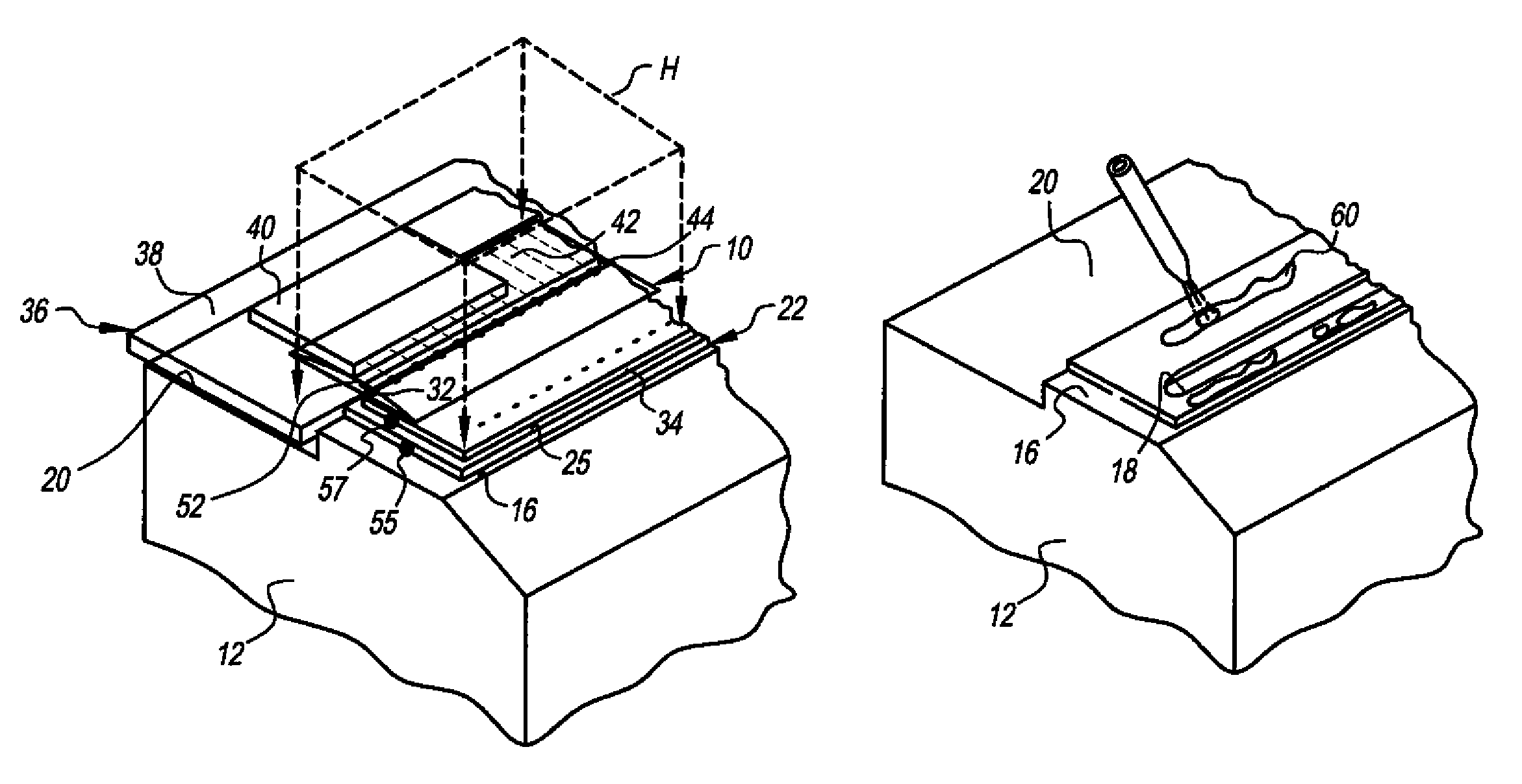
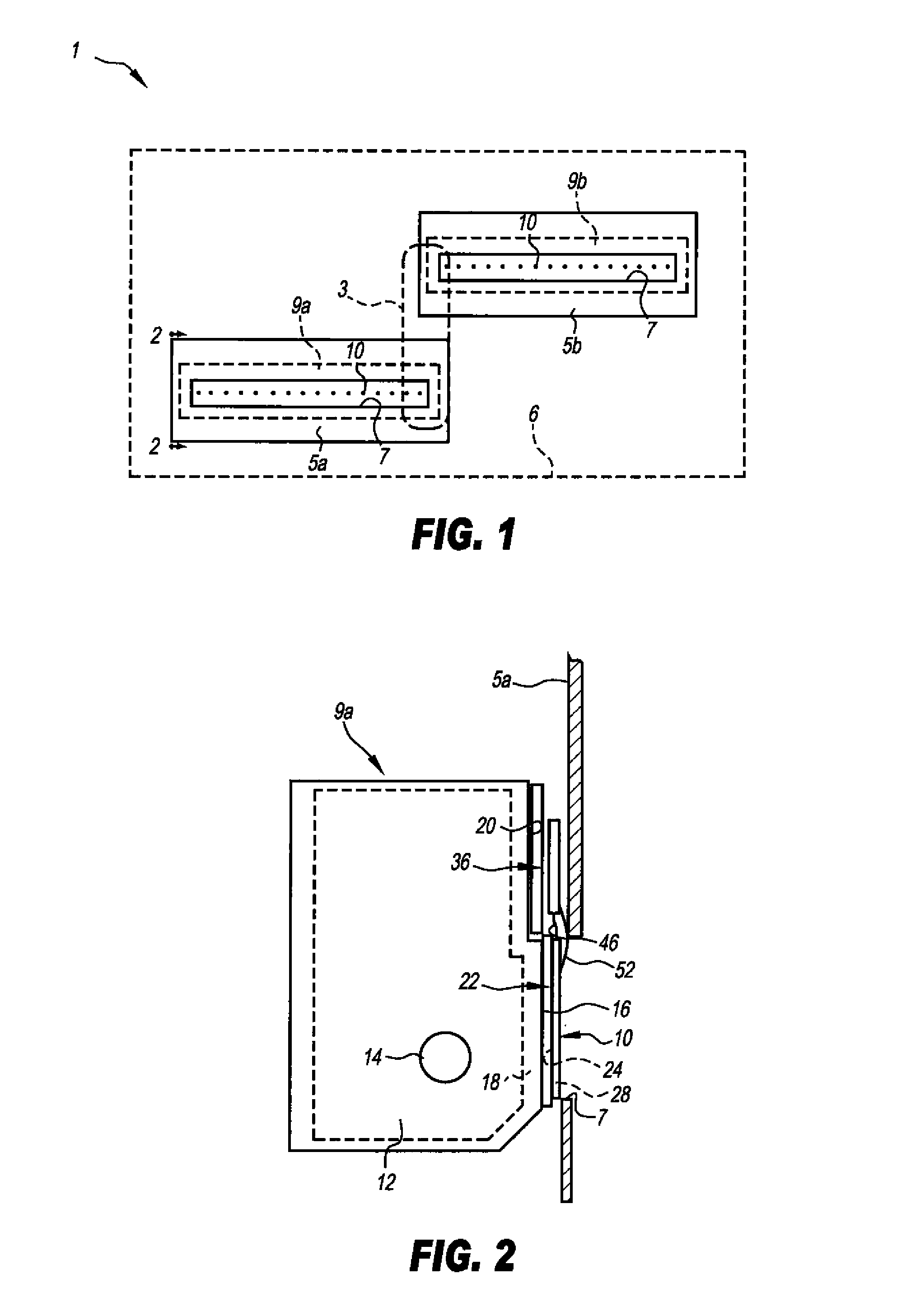
The invention is a recyclable continuous ink jet print head which uses an interposer member formed from a material having a coefficient of thermal conductivity that is equal to or greater than the material forming the die and a coefficient of thermal expansion (CTE) that is between the CTE of the manifold and the CTE of the die. Such an interposer member would allow more durable heat curable epoxy adhesives to be used to bond the die and the manifold and to encapsulate the microwiring between the die and the control circuit while still allowing the die to be easily removed from the manifold so that the manifold may be recycled.
To solve the misalignment problem, the invention provides an interposing member between the die and the manifold having a CTE about halfway between the CTE of the die and manifold. Such an interposing member reduces the amount of thermally-induced shifting of the die on the manifold caused by the heat curing of an epoxy adhesive by a factor of about one-half.
Finally, the invention encompasses an assembly and recycling method for a continuous ink jet print heat. The method generally includes the steps of applying a thermally curable epoxy material between an interposing member and the manifold and the interposing member and the die and over the microwiring connecting the electrodes in the die to the integrated control circuit. The epoxy material is then heat cured to a temperature of between about 50° C. and 130° C. The intermediate CTE of the interposing member reduces nozzle misalignment caused by such heat curing to within acceptable tolerances. At the end of the service life of the resulting print head, localized heat is applied to the interposing member to loosen the epoxy material bonding the interposing member to the manifold. The relatively high thermal conductivity of the interposing member efficiently directs the localized heat to the epoxy bond, effectively softening it. The die is then removed along with the interposer, and residual epoxy material is abraded off of the surface of the manifold, resulting in the recycling of the most expensive component of the print head module.

Problems solved by technology

However, the applicant has observed that the heat curing step frequently causes misalignment between the die and the manifold due to the difference in the coefficient of thermal expansion (CTE) between the silicon forming the die and the stainless steel forming the manifold.
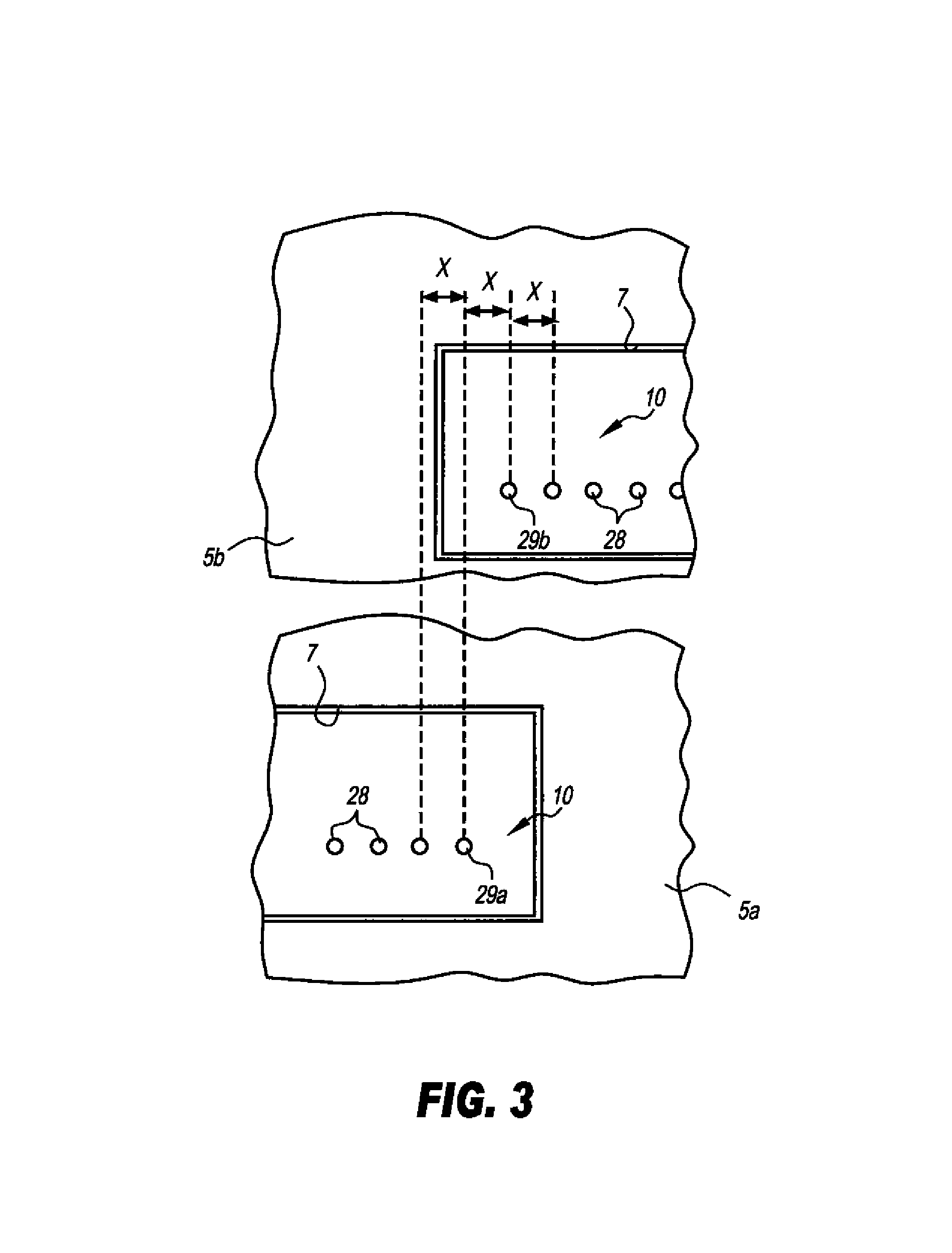
The resulting misalignment often causes the spacing between the last ink jet on one die to be spaced too far away or too close to the first jet on the other die when the manifolds of the two modules are positioned end-to-end, thus potentially degrading the quality of the printing at the joint between the two dies.
However, applicant has observed that the low thermal conductivity associated with such ceramic materials substantially interferes with the transfer of heat between the die and the epoxy material bonding the die to the manifold.
Such low thermal conductivity necessitates exposure of the entire manifold to high temperatures before the die can be removed, and this can corrode and warp the manifold to the extent that it becomes unusable.

Method used


Image

  • Recyclable continuous ink jet print head and method
  • Recyclable continuous ink jet print head and method
  • Recyclable continuous ink jet print head and method

Examples


example 1 (

Control)

A 4.3 inch long Si die containing nozzles and microelectronics circuitries was bonded to a stainless steel manifold using Hysol QMI 550EC adhesive (from Henkel Corporation, San Diego, Calif.), Before curing the die bond, the distance between the center of the first to the center of the last, or 2560th, nozzle was measured by a Smartscope Quest 650, made by Optical Gauging Products, Rochester, N.Y.), and found to be 108.324 (+−0.0005) mm. After curing to 120 C for 1 hr, and cooling to room temperature, the same measurement was found to be 108.262 mm. The array of nozzles had shrunk by 62 microns. The high curing temperature produced a relatively large dimensional change in the die that is outside of acceptable tolerances.

example 2 (

Control)

A 4.3 inch long Si die containing nozzles and microelectronics circuitries was bonded to a stainless steel manifold using QMI 536 1A2 adhesive (from Henkel Corporation, San Diego, Calif.). Before curing, the distance between the center of the first to the center of the last, or 2560th nozzle was measured to be 108.323 millimeters. After thermal curing to 80 C for 2 hr, and then cooling to room temperature, the distance between the first to the last or 2560th nozzle was measured to be 108.290 millimeters. The nozzle array had shrunk by 33 microns. By going to a lower curing temperature, the CTE mismatch between the die and the manifold manifested relatively less dimensional change. However, the dimensional change of 33 microns is still outside the range of acceptable tolerances.

example 3 (

Invention)

An Al / SiC interposer (made of MCX-724, from Thermal Transfer Composite LLC, Newark, Del.) cut to the same outer dimension as the 4.3 inch long Si die, was bonded to the stainless steel manifold using QMI 536 1A2 adhesive. This was then treated at 80 C, for 2 hr. Then a 4.3 inch long Si die containing nozzles and microelectronics circuitries was bonded to the Al / SiC interposer using QMI 536 1A2 adhesive. Before curing, the distance between the center of the first to the center of the last, or 2560th, nozzles was measured to be 108.323 millimeters. After thermal curing to 80 C, for 2 hr, and then cooling to room temperature, the distance between the first to the last, or 2560th nozzle was measured to be 108.307 millimeters. The nozzle array had shrunk by 16 microns. By going to a lower curing temperature, and using an interposer with a CTE approximately half way between those of the manifold and the die, the dimensional change is reduced to within acceptable tolerances.

For m...


PUM

PropertyMeasurementUnit
temperatureaaaaaaaaaa
distanceaaaaaaaaaa

Abstract

A recyclable continuous ink jet print head is provided that includes a manifold formed from a metal such as stainless steel, a die having ink jet nozzles formed from a ceramic material such as silicon, a control circuit connected to the die via microwiring, and an interposing member disposed between the manifold and the die. The interposing member is formed from a composite material such as Al—SiC having a coefficient of thermal conductivity that is higher than that of the silicon die, and a coefficient of thermal expansion (CTE) that is between that of the die and the manifold. During manufacture, the CTE value of the interposing member allows long-lasting, heat-cured epoxy compositions to be used to bond the die to the manifold and to encapsulate the microwiring between the die and a control circuit with while maintaining proper alignment of the die ink jet nozzles on the manifold. When the die wears out, the high thermal conductivity of the interposing member allows the die to be easily removed from the manifold, thereby facilitating re-cycling of the manifold.

Description

FIELD OF THE INVENTIONThis invention generally relates to continuous ink jet print heads, and is specifically concerned with the use of an interposer member between the manifold and the die of a continuous ink jet print head module that results in a more durable print head and facilitates both assembly and recycling of the print head components.BACKGROUND OF THE INVENTIONInk jet printing has become recognized as a prominent contender in the digitally controlled, electronic printing arena because, e.g., of its non-impact, low-noise characteristics, its use of plain paper and its avoidance of toner transfer and fixing, as well as its very fast printing speed. Ink jet printing mechanisms can be categorized by technology as either drop on demand ink jet or continuous ink jet.The first technology, “drop-on-demand” ink jet printing, provides ink droplets that impact upon a recording surface by using a pressurization actuator (thermal, piezoelectric, etc.). Many commonly practiced drop-on-...

Claims


Application Information

Patent Timeline
Patent Type & Authority Patents(United States)
IPC IPC(8): B41J2/135
CPCB41J2/1408B41J2/145B41J2002/14362B41J2202/20
Inventor CHEN, SAMUELSTOKER, STEPHEN C.PHELAN, GIANA M.
Owner EASTMAN KODAK CO
Learn More