Cable lubrication device

a lubrication device and cable technology, applied in the direction of shafts, cycle equipments, shafts, etc., can solve the problems of wasting lubricant, affecting the service life of the device, so as to minimize the waste of lubricant, direct the flow of lubricant, and minimize the effect of spraying

Active Publication Date: 2017-01-05
MOTION PRO
View PDF2 Cites 1 Cited by
  • Summary
  • Abstract
  • Description
  • Claims
  • Application Information

AI Technical Summary

Benefits of technology

[0009]An advantage of the present invention is that it directs the flow of lubricant very efficiently.
[0010]Another advantage of the present invention is it minimizes spray of lubricant on the user's hands and clothing.
[0011]And another advantage of the present invention is it minimizes the waste of lubricant by directing it better to the areas of concern.
[0012]A further advantage of the present invention is there is a better seal formed with the pressurized source of lubricant, and therefore more pressure is concentrated into the cable, helping to push out debris that has formed inside the cable sleeve.
[0013]A yet further advantage of the present invention is that since there is a better seal formed between the device and the pressurized lubricant source, the lubricant is more evenly dispersed throughout the internal space of the control cable.
[0014]A still further advantage of the present invention is that since there is a better seal formed between the device and the pressurized lubricant source, there is less leakage of excess lubricant onto the user, and thus less exposure to hazardous chemicals during the lubrication process.

Problems solved by technology

This mating was generally difficult since cables come in a variety of sizes and the nozzle of the lubricant can was not adaptable to this variety of configurations.
Thus, the lubrication operation was usually a messy affair, which got a lot of lubricant on the user's hands or clothing and wasted a lot of mis-directed lubricant.
However, in practice, these devices have not been able to provide anything close to a liquid tight seal against the inner wire of the cable because most inner wires consist of multiple strands of wire that are spiral wound and have flutes that allow liquid to go past the seal no matter how tightly it is clamped down onto the inner wire.
In addition, in practice, the slit in the tapered sleeve is difficult to clamp together to prevent leakage of fluid because they cannot accommodate the large variations in cable housing diameter.
As a result, in use, these devices leak substantial amounts of lubricant and allow substantial portions of the lubricant to be ejected from the device, and only the portion of the lubricant that is put in the device is actually forced into the cable that is being serviced.
As a result, the existing device is very messy to use, does not make efficient use of lubricant, and does not allow complete cleaning or lubrication of the cable being serviced.

Method used


Image

  • Cable lubrication device
  • Cable lubrication device
  • Cable lubrication device

Examples


Embodiment Construction

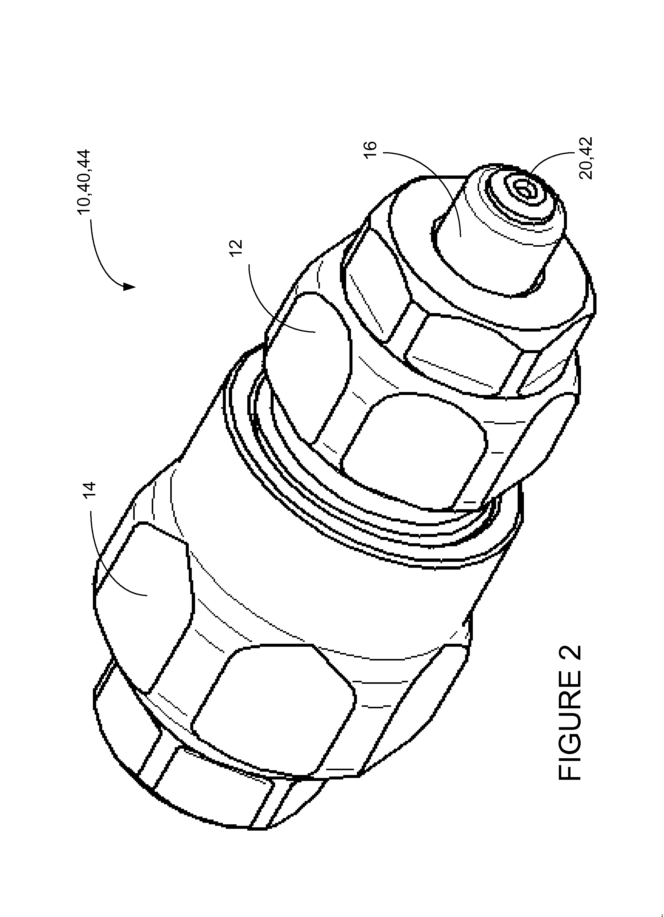
[0024]The present invention is cable lubrication device, which will be referred to by the reference number 10, and thus shall be referred to as cable lubricator 10. A preferred embodiment of the cable lubricator 10 is illustrated in FIGS. 2-8.

[0025]FIGS. 2-4 shows the present cable lubricator 10, with FIG. 2 showing an isometric view, FIG. 3 showing a plan view and FIG. 4 showing a cut away view taken through line A-A of FIG. 3. The cable lubricator 10 includes a main body tube 12, a locking ring 14, a plunger 16, a spiral-cut seal 18, and a plunger plug 20.

[0026]As best seen in cut-away view of FIG. 4, the main body tube 12 and the locking ring 14 are joined together by screw threads 22, by which the locking ring 14 can be screwed down onto the main body tube 12. Inside the cable lubricator 10, there is a spiral-cut seal 18, which is compressed inwardly when the locking ring 14 is advanced on the screw threads 22 towards the main body tube 12. The spiral-cut seal has a central cavi...


PUM


Abstract

A cable lubrication device for directing pressurized lubricant into the internal space of a control cable, the cable lubrication device having a main body tube, a locking ring, a plunger and a spiral-cut seal.

Description

TECHNICAL FIELD[0001]The present invention relates generally to devices for maintaining and servicing mechanical parts and more particularly to tools for lubrication of cables in motorcycles or other wheeled vehicles.BACKGROUND ART[0002]Many motorized vehicles use cables to control certain functions of the machine, such as to actuate the throttle, clutch and brakes. A block drawing of a control cable is shown in FIG. 1. These control cables 1 generally include a central wire 2, which is surrounded by a protective sleeve 3, which also provides anchoring points for the overall assembly, whereby the sleeve 3 is fixed in position while the internal wire 2 is allowed to slide within. There is an internal space 4 between the inner side of the sleeve 3 and the outer surface of the wire 2, within which the wire 2 moves relative to the sleeve 3. The wire 2 also usually has a fitting 5 attached to the end of the wire 2, which is captured in a notch in some control mechanism, such as throttle,...

Claims


Application Information

Patent Timeline
Patent Type & Authority Applications(United States)
IPC IPC(8): F16C1/24
CPCB62J31/00F16C1/107F16C1/24
Inventor SCOTT, STEVEN RICHARD
Owner MOTION PRO
Why Eureka
Try Eureka