

Centrifugal Pump
- Summary
- Abstract
- Description
- Claims
- Application Information
AI Technical Summary
Benefits of technology
Problems solved by technology
Method used
Image

Examples
Embodiment Construction
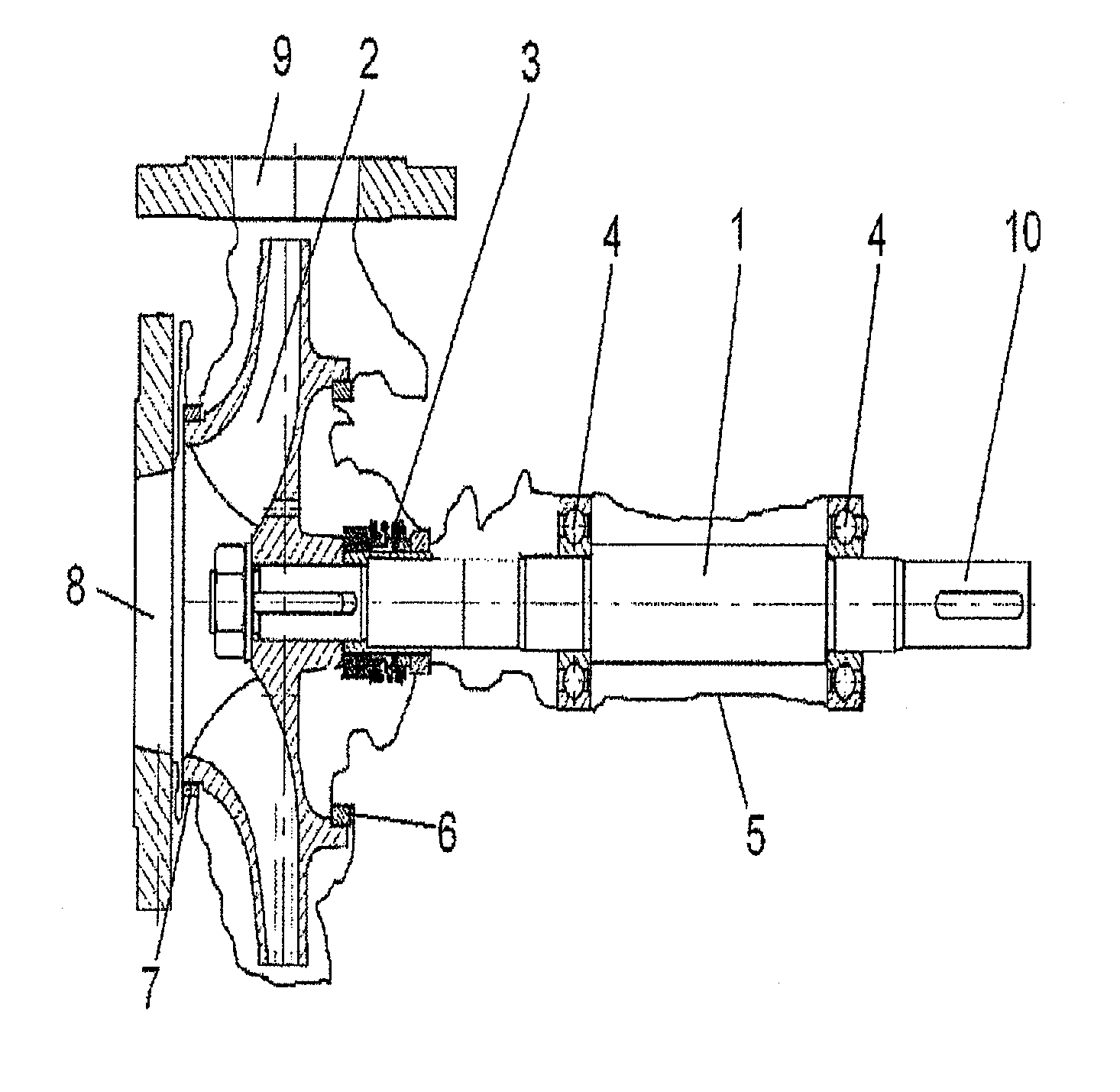
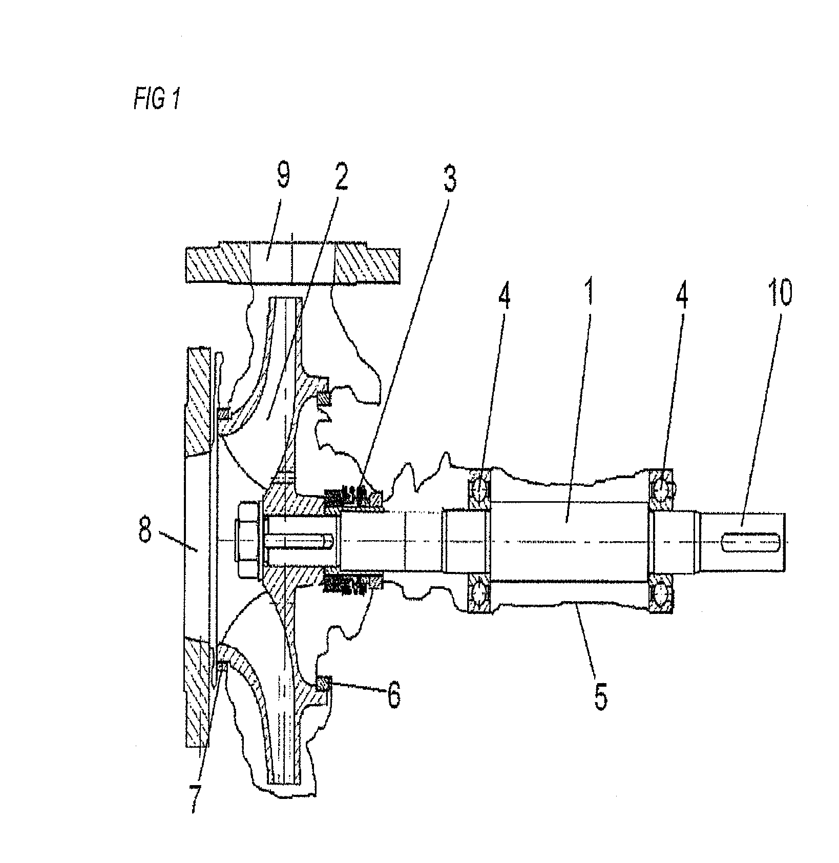
[0040]FIG. 1 shows an embodiment of a centrifugal pump according to the invention. An impeller 2 is fastened at the left end of a shaft 1. A seal 3 is arranged so as to be connected directly to the impeller 2. A bellows-type floating ring seal is illustrated in FIG. 1. That part of the seal 3 which is adjacent the impeller 2 is connected firmly to the shaft and co-rotates with the shaft. The stationary part, connected to a casing, of the floating ring seal is arranged at far right. Two bearings 4 are arranged on the shaft 1 at some distance from the seal 2. In a construction kit for this version of the centrifugal pump, all the parts which must satisfy special requirements as to dimensional tolerances are premounted with an exact fit. A first layer 5 sheaths the parts and forms the inner wall of the pump casing. To form the various portions of the pump casing, the first layer 5 is connected directly to some pump parts, while the first layer 5 may also be of multipart construction, i...
PUM
| Property | Measurement | Unit |
|---|---|---|
| Time | aaaaa | aaaaa |
| Pressure | aaaaa | aaaaa |
| Electrical resistance | aaaaa | aaaaa |
Abstract
Description
Claims
Application Information