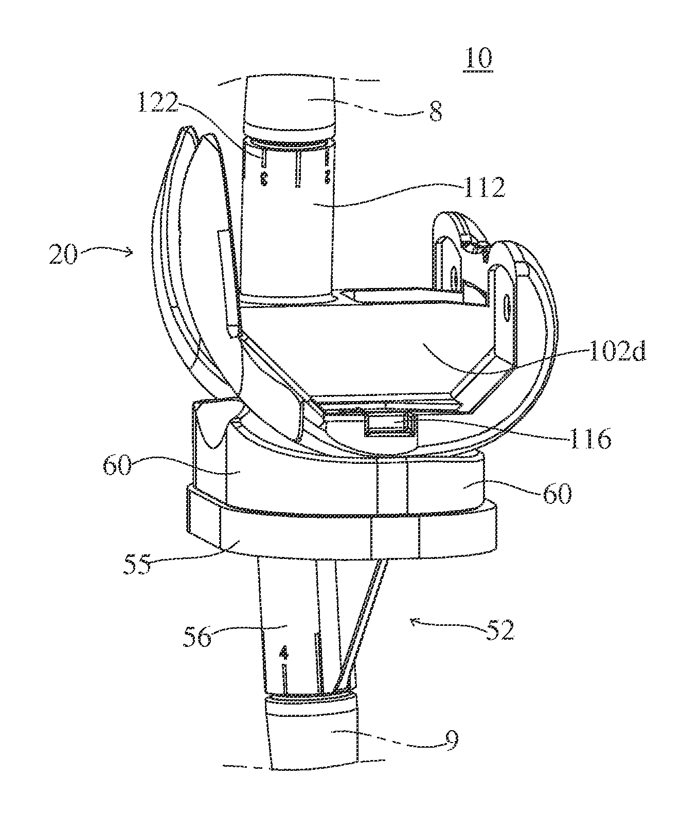
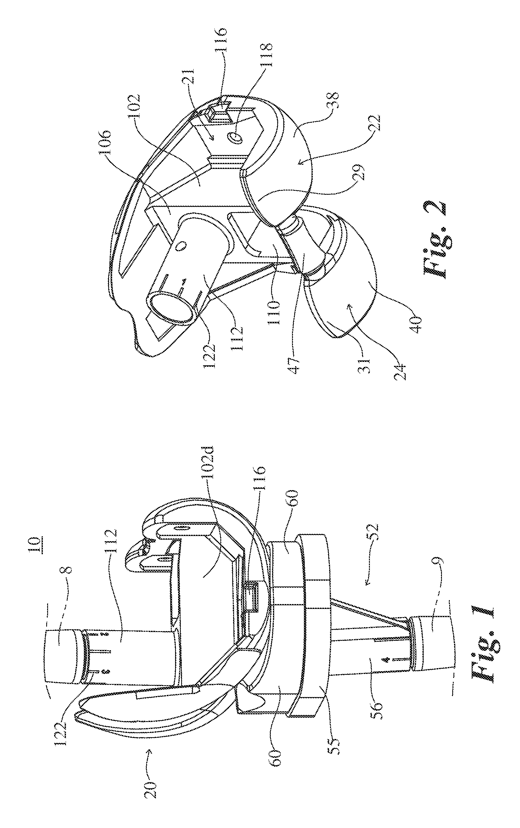
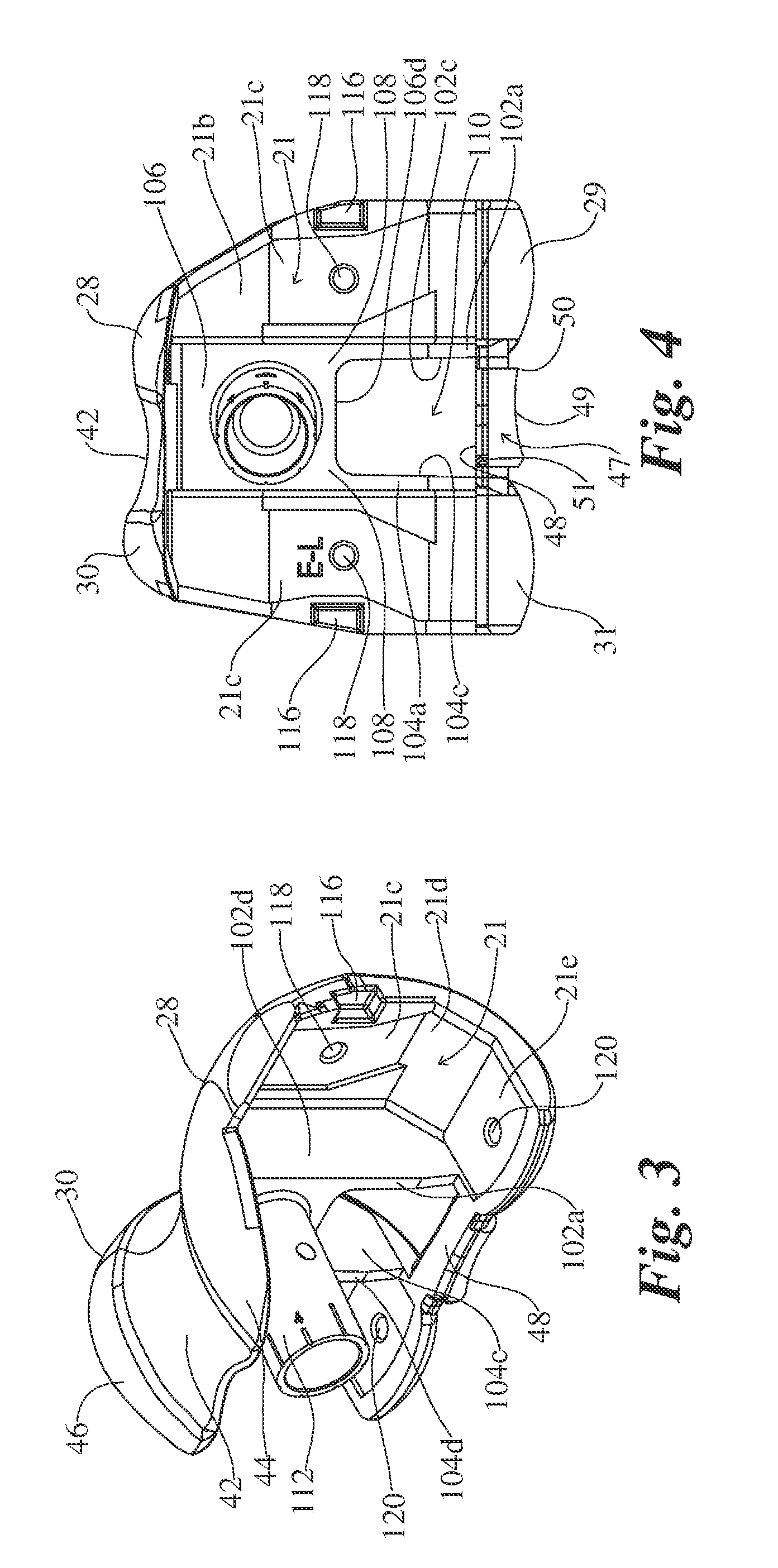
Knee Revision Prosthesis With Progressive Restraint

a knee joint and prosthesis technology, applied in knee joints, knee replacement, medical science, etc., can solve the problems of prosthesis replacement, weakening or degrading the anatomy to which the primary prosthesis is attached, and the primary prosthesis may simply wear out or be damaged by patient trauma, etc., to achieve increased laxity, reduced restraint, and increased restraint

Inactive Publication Date: 2013-05-16
MAXX ORTHOPEDICS INC
View PDF4 Cites 3 Cited by
  • Summary
  • Abstract
  • Description
  • Claims
  • Application Information

AI Technical Summary

Benefits of technology

[0008]The invention comprises a revision knee prosthesis that provides variable restraint restraint as the knee rotates through its normal range of motion. In a first embodiment, the revision knee replacement prosthesis provides decreased restraint (increased laxity) as the knee rotates from full extension to flexion, and then provides increased restraint (decreased laxity) as the knee rotates from flexion to full extension. In a preferred embodiment, variation in restraint relates to valgus-varus laxity (rotation or tilt in the coronal plane) and / or medial-lateral laxity (rotation in the transverse plane).
[0009]The novel prosthesis comprises a femoral component that articulates with a tibial component and the natural or prosthetic patella. In a first embodiment, the revision knee prosthesis comprises a femoral component that connects to the distal end of a resected femur and a tibial component that connects to the proximal end of a resected tibia. The femoral component includes medial and lateral condyles having distal, articulating condylar surfaces, and a patellar flange having an articulating patellar surface. The tibial component includes a proximal bearing surface with medial and lateral concavities that articulate with the medial and lateral condyles. The condylar surfaces and concavities enable anterior-posterior translation of the femur relative to the tibia, and enable the tibia to rotate about its longitudinal axis during flexion of the knee.
[0010]The femoral component includes a guide box fixed to the femoral mounting surfaces intermediate the condyles. The tibial component includes a central post fixed intermediate the tibial concavities, which articulates within the guide box and constrains rotational movement of the femoral and tibial components relative to one another in the coronal plane and transverse planes. The post and guide box are constructed and arranged to provide progressively decreasing and then progressively increasing rotational restraint of the femoral component in the coronal and transverse planes as the femoral component rotates in the sagittal plane between full extension to a position in flexion, and then back to full extension, respectively. In a preferred embodiment, the femoral component is restrained from rotating or tilting more than about 2 degrees in the coronal plane when the prosthesis is positioned in full extension and from rotating or tilting more than about 7 degrees in the coronal plane when the prosthesis is positioned in full flexion.

Problems solved by technology

For example, the primary prosthesis may simply wear out or be damaged from patient trauma.
However, the most common condition requiring primary prosthesis replacement is weakening or degradation of the anatomy to which the primary prosthesis is attached, which is commonly caused by osteolysis.
In such case, it is usually not possible to surgically re-attach the primary prosthesis since the bone has typically degraded to a condition that is incompatible for re-connection to a primary device.
Furthermore, the patient's bone is further degraded when the primary prosthesis, which is typically cemented to the bone, is removed by chipping away at the bone.
Some prior art revision prostheses have very little clearance between the post and the guide box, which provides the desirable high level of constraint in full extension but undesirable high level of constraint during flexion.
On the other hand, other prior art revision prostheses have greater clearance between the post and the guide box, which provides undesirable laxity in full extension but desirable laxity during flexion.
It is believed, however, that none of the prior art revision prostheses provide high restraint during full extension and reduced restraint during flexion.

Method used


Image

  • Knee Revision Prosthesis With Progressive Restraint
  • Knee Revision Prosthesis With Progressive Restraint
  • Knee Revision Prosthesis With Progressive Restraint

Examples


Embodiment Construction

[0036]For the purpose of illustrating the invention, several embodiments of the invention are shown in the accompanying drawings. However, it should be understood by those of ordinary skill in the art that the invention is not limited to the precise arrangements and instrumentalities shown therein and described below. Throughout the specification, like reference numerals are used to designate like elements. Numerous changes and modifications within the spirit and scope of the invention will become apparent to those skilled in the art from this detailed description.

[0037]Unless otherwise defined, all technical and scientific terms used herein in their various grammatical forms have the same meaning as commonly understood by one of ordinary skill in the art to which this invention belongs. The terms varus, valgus, anterior, posterior, proximal, distal, medial, lateral, sagittal, coronal, and transverse are used herein with their conventional medical / anatomical meaning as defined, for ...


PUM


Abstract

A knee revision prosthesis that provides decreasing valgus-varus and medial-lateral restraint as the knee rotates from extension to flexion, and then increasing restraint as the knee rotates from flexion to full extension. The prosthesis includes a femoral component and a tibial component. The femoral component includes a guide box fixed to the femoral mounting surfaces intermediate the condyles. The tibial component includes a central post fixed intermediate the tibial concavities, which articulates within the guide box and constrains rotational movement of the femoral and tibial components relative to one another in the coronal plane and transverse planes. The post and guide box are constructed and arranged to provide progressively decreasing and then progressively increasing rotational constraint of the femoral component in the coronal and transverse planes as the femoral component rotates in the sagittal plane between full extension to a position in flexion, and then back to full flexion, respectively.

Description

FIELD OF THE INVENTION [0001]The present invention relates to a revision knee prosthesis that provides decreasing coronal and transverse rotational constraint as the knee rotates from extension to flexion, and then increasing constraint as the knee rotates from flexion to full extension.[0002]Knee revision surgery, also known as revision total knee arthroplasty, is a procedure in which the surgeon removes a previously implanted artificial knee joint, or “primary” prosthesis, and replaces it with a new “revision” prosthesis. Replacement of the “primary” prosthesis is required when it becomes defective or its connection to the femur and / or tibia becomes compromised (loosened), both of which may occur for several reasons. For example, the primary prosthesis may simply wear out or be damaged from patient trauma. However, the most common condition requiring primary prosthesis replacement is weakening or degradation of the anatomy to which the primary prosthesis is attached, which is comm...

Claims


Application Information

Patent Timeline
Patent Type & Authority Applications(United States)
IPC IPC(8): A61F2/38
CPCA61F2/3886
Inventor SHAH, ASITPERINE, COREY ANTHONY
Owner MAXX ORTHOPEDICS INC
Why Eureka
Try Eureka