
Device for limiting the consequences of a widespread fire in premises

a technology of premises fire and passive devices, which is applied in the direction of dental surgery, nuclear engineering, separation processes, etc., can solve the problems of reducing the reliability of the structure already weakened, affecting the performance of the elements, and reducing so as to improve the reliability of the device's operation, the effect of reducing the risk of fire and reducing the risk of spreading dangerous materials

Inactive Publication Date: 2013-05-23
COMMISSARIAT A LENERGIE ATOMIQUE ET AUX ENERGIES ALTERNATIVES
View PDF2 Cites 1 Cited by
  • Summary
  • Abstract
  • Description
  • Claims
  • Application Information

AI Technical Summary

Benefits of technology

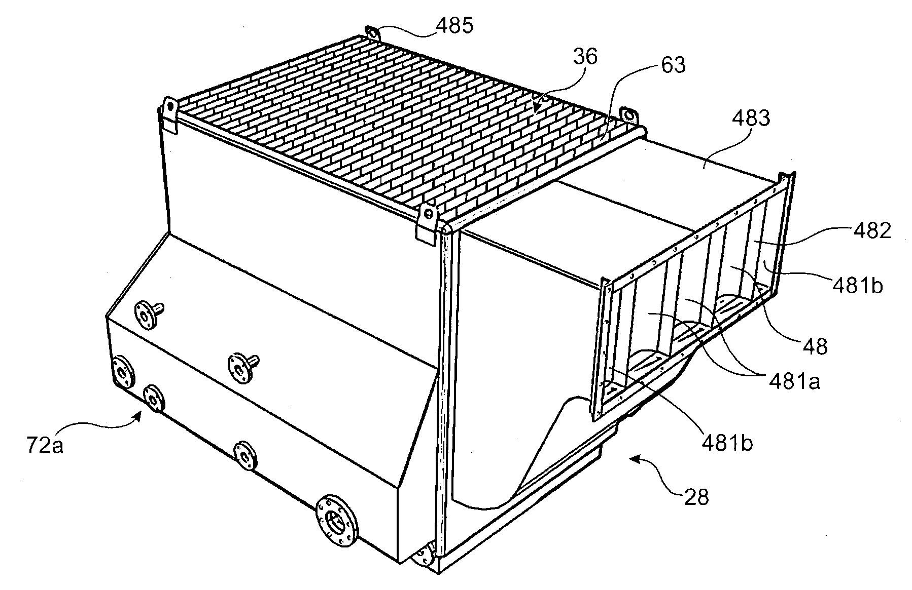
The patent describes a system that uses overflow tanks to control the pressure in a room, regardless of the gas flow or liquid level. This system allows for a simple and reliable device that can handle sudden changes in liquid level. The use of overflow tanks also simplifies the liquid-supply circuit and increases the device's flexibility and responsiveness. Additionally, the system includes a retardation chamber, droplet catcher, bubbling chamber, and anti-spatter devices to prevent liquid splashing. The patent also mentions the use of a regulation system with a float valve to compensate for evaporation. Overall, the system provides a more efficient and reliable way to control pressure in a room.

Problems solved by technology

The above extreme conditions give rise to a risk of dissemination of the dangerous materials to the confinement enclosure and to the environment, and propagation of the fire to the rest of the plant.
This high negative pressure in the storage cell can also call into question the integrity of the structures already weakened by the extreme conditions of the fire.
In some cases, fixed extinguishing systems, for example of the gas type, are liable to create, by expansion in the storage cell, an overpressure capable of impairing the performance of the elements participating in the static barrier.
In other cases, a fire may cause rupture of a container under pressure, putting in danger the elements participating in the static barrier in the same way as in the previous cases.
In addition, the features of this device mean that the gas flow rates that can be treated are limited.

Method used


Image

  • Device for limiting the consequences of a widespread fire in premises
  • Device for limiting the consequences of a widespread fire in premises
  • Device for limiting the consequences of a widespread fire in premises

Examples


example embodiment

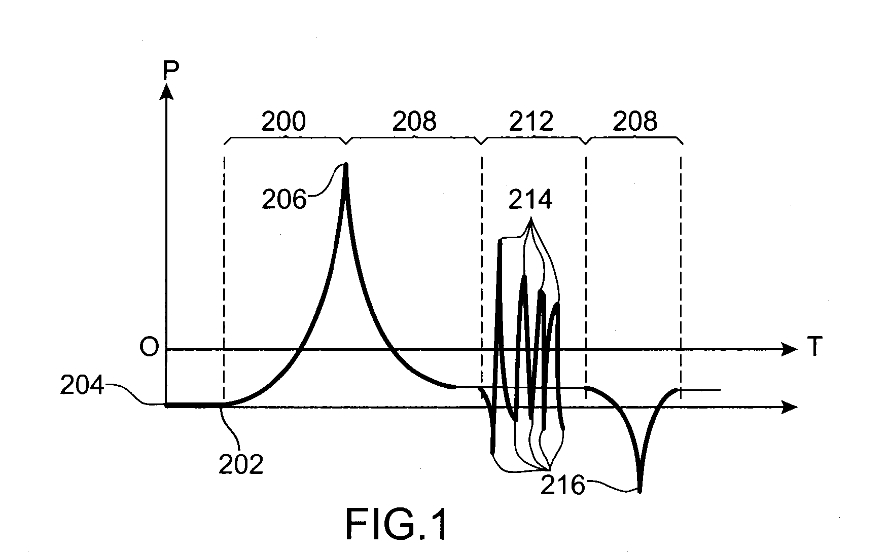
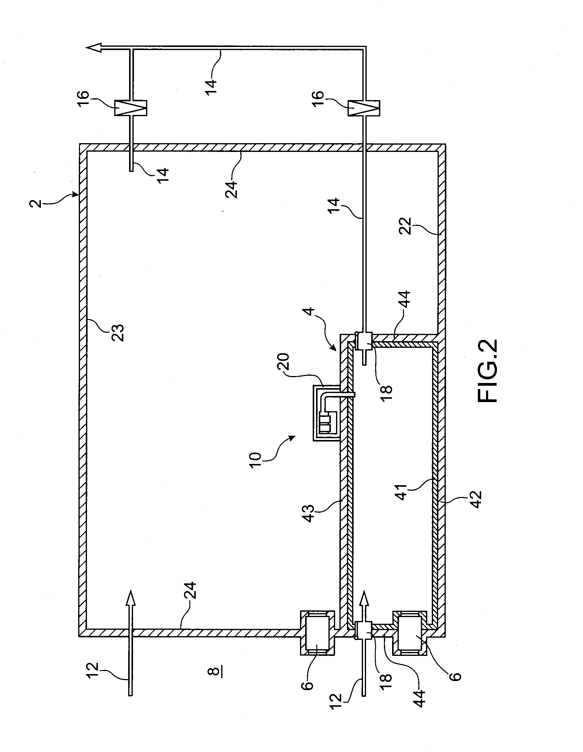
[0128]The various components of the limitation device 10 are normally sized on the basis of an envelope assessment of the maximum thermodynamic conditions of a widespread uncontrolled fire in a storage cell 4. This prior study makes it possible to determine the triggering pressure thresholds p-ech and p_adm of the limitation device 10 and the flow rate that has to escape through the limitation device 10 in order to maintain the pressure of the storage cell 4 at a pressure less than the “safety pressure” Ps of the confinement members, that is to say the fire-stop shutters, the air lock doors and the partitions.

[0129]An example of sizing is provided below, considering a widespread fire with very slow kinetics, which may be the case for waste packaged in metal barrels.

[0130]safety pressure Ps of the confinement members; + / −2100 Pa,

[0131]volume of the confinement chamber 2: 15000 m3,

[0132]volume of the storage cell: 3000 m3,

[0133]rate of renewal of the ventilation: 2 volumes / h,

[0134]tri...


PUM

PropertyMeasurementUnit
Heightaaaaaaaaaa
Levelaaaaaaaaaa

Abstract

A device for limiting consequences of a fire, in a room, including a reservoir including a vessel containing a liquid, the reservoir including one or more chambers in communication with a storage cell and one or more other chambers. The reservoir also includes at least a first overflow tank and at least a second overflow tank, both integral, placed on either side of the reservoir, each tank configured to receive the liquid when the liquid exceeds a predetermined given height in the vessel.

Description

TECHNICAL FIELD[0001]The present invention relates to the field of passive devices for limiting the consequences of a fire, devices that guarantee the non-propagation of the heat or flame and the filtering of the discharged gases, and limit the phenomena of overpressure or negative pressure when a fire is declared and which may be caused by the fire itself, or by a device for extinguishing this fire, or by the failure of another apparatus.[0002]More particularly, it concerns a device suitable for installations that must maintain the resistance of an enclosure or room to effects of overpressure or an excess of negative pressure, while guaranteeing non-propagation of the heat or flame.PRIOR ART[0003]In plants that hold and confine dangerous materials, the environmental protection requirements make it necessary to enclose these dangerous materials by placing them in a suitable confined room. Such a room may be in the form of a storage cell.[0004]The environmental protection requirement...

Claims


Application Information

Patent Timeline
IPC IPC(8): A62C2/00
CPCA62C3/00A62C4/00B01D46/10G21F7/015A62C2/00G21F7/00B01D46/02G21F9/00
Inventor BOIS, DOMINIQUENEUMAN, MATHIEUDELAFORGE, THIERRY
Owner COMMISSARIAT A LENERGIE ATOMIQUE ET AUX ENERGIES ALTERNATIVES
Learn More