
Apparatus having a controllable filter matrix to selectively acquire different components of solar irradiance

a filter matrix and filter technology, applied in the direction of optical radiation measurement, radiation control devices, instruments, etc., can solve the problems of affecting the reliable operation of the sensor, and affecting the accuracy of the measuremen

Inactive Publication Date: 2013-05-23
GENERAL ELECTRIC CO
View PDF2 Cites 16 Cited by
  • Summary
  • Abstract
  • Description
  • Claims
  • Application Information

AI Technical Summary

Benefits of technology

The present invention provides an apparatus for selectively acquiring different components of solar irradiance using a filter matrix. This apparatus can control which part of the solar irradiance is passed through the filter matrix, based on the position of the sun or other light sources in its field of view. The apparatus can also use a photosensor and controller to selectively attenuate direct sunlight and create an image free from image defects caused by this sunlight. Additionally, a method is provided for controlling the filter matrix to selectively acquire different components of solar irradiance, based on their position in the field of view. Overall, the invention allows for more precise and accurate detection and measurement of solar energy.

Problems solved by technology

In the case of measurements of diffuse irradiance, it is known to use some kind of mechanically-rotatable shadowing device, where a shadowing mechanical structure, such as ball, ring or band, generally involves a costly and complicated mechanical contraption to meet a required mechanical tracking accuracy, which may be difficult to consistently realize over a long period of time in the outdoors.
A further undesirable characteristic of such devices may be measurement errors introduced by the shadowing mechanical structure, which may physically block at least some of the field of view needed to accurately capture the diffuse irradiance component.
In the case of measurements of direct irradiance, high-intensity irradiance may cause sensor burn-in effects which may shorten reliable operation of a sensor over time.

Method used


Image

  • Apparatus having a controllable filter matrix to selectively acquire different components of solar irradiance
  • Apparatus having a controllable filter matrix to selectively acquire different components of solar irradiance
  • Apparatus having a controllable filter matrix to selectively acquire different components of solar irradiance

Examples


Embodiment Construction

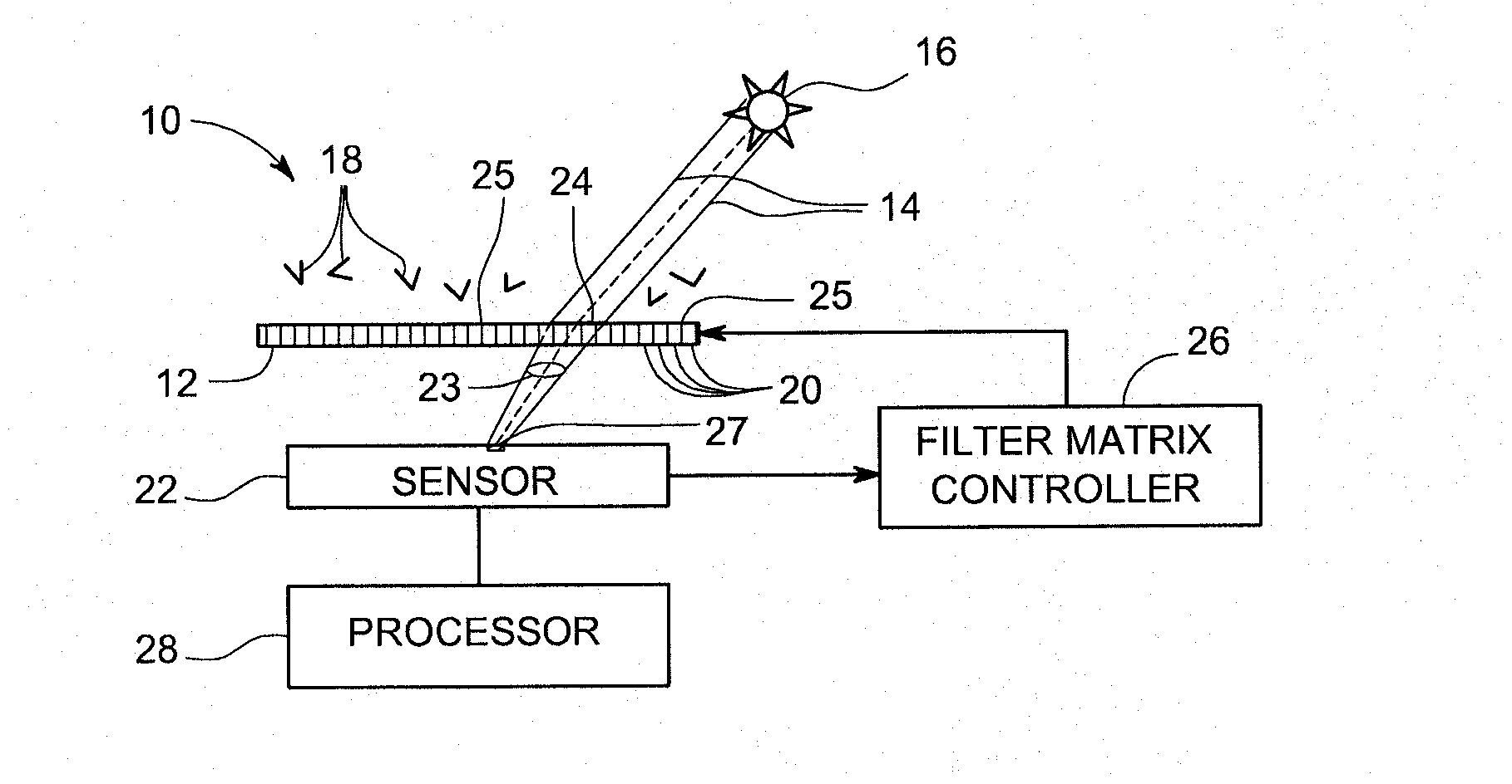
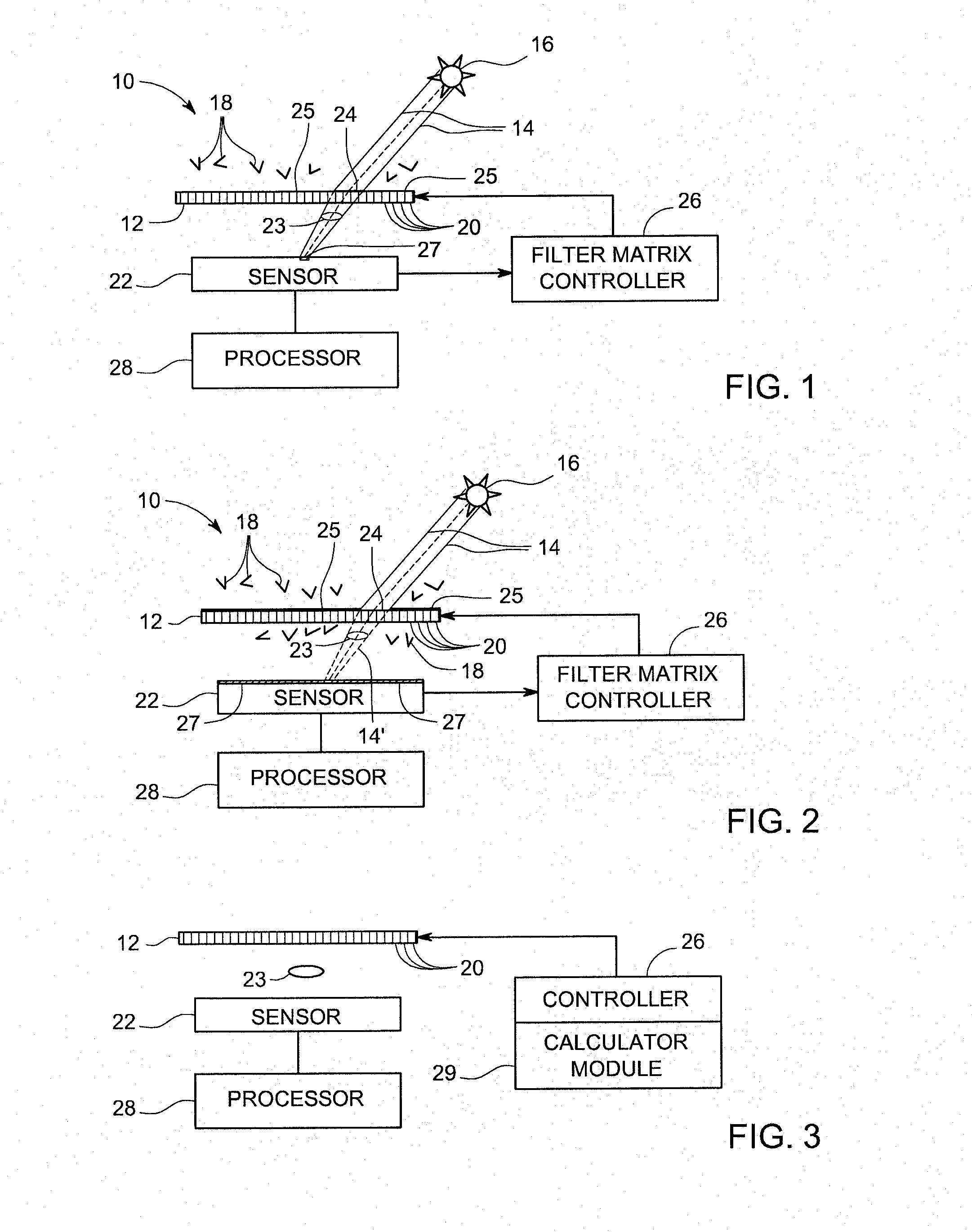
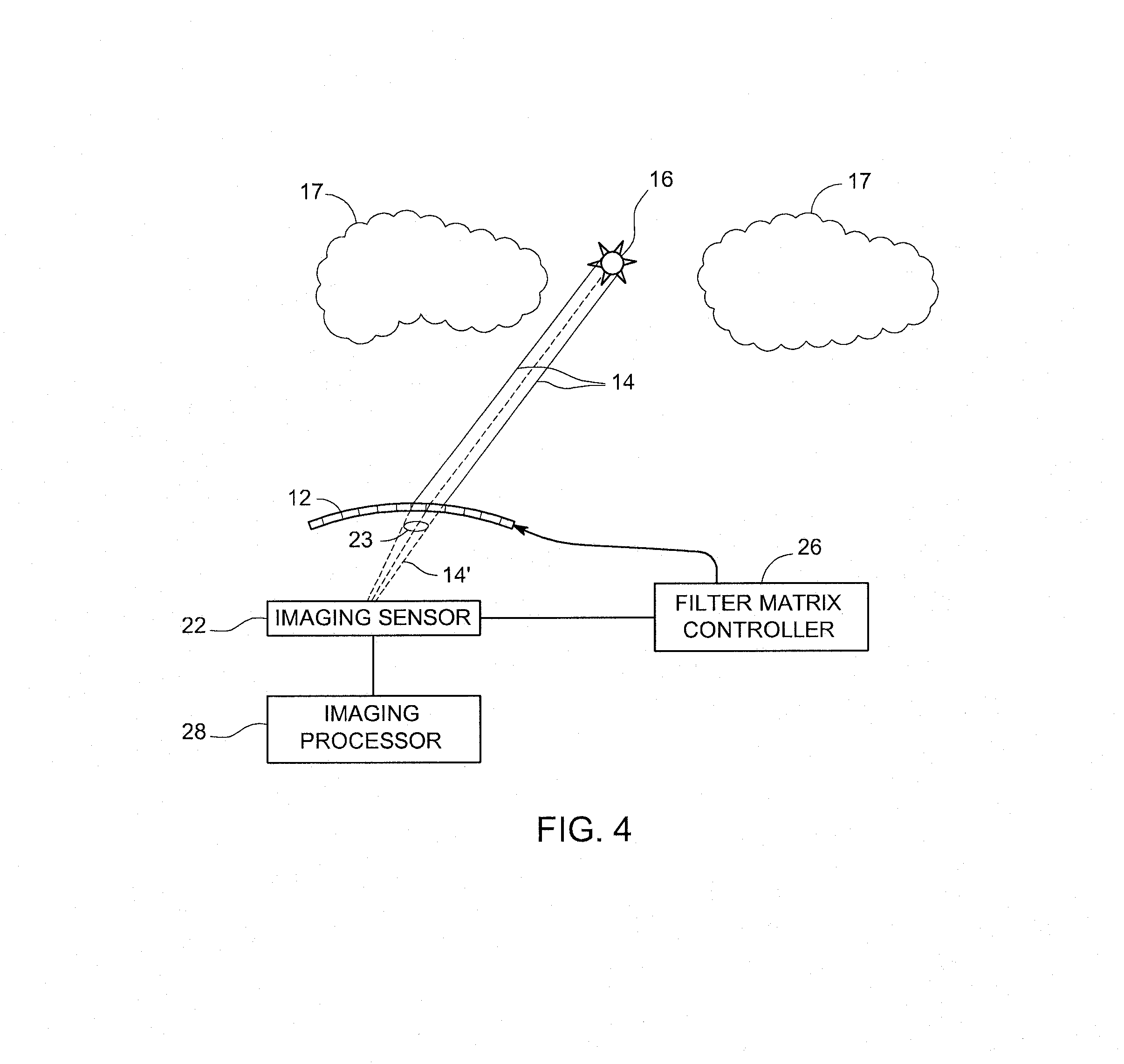
[0015]FIG. 1 shows a schematic representation of an example embodiment of an apparatus 10 embodying aspects of the present invention. A filter matrix 12 may be arranged to receive incident solar irradiance, such as a direct irradiance component (symbolically represented by light beams 14 from the sun 16) and a diffuse irradiance component (symbolically represented by a plurality of multidirectional arrow heads 18). Filter matrix 12 may comprise an array of pixels 20 controllable (e.g., electrically controllable) to selectively acquire different components of such solar irradiance component. For example, the array of pixels 20 may be controllable to provide a selectable field of view to selected different components of the solar irradiance.

[0016]Example embodiments of filter matrix 12 may include any of a variety of pixelated arrays, such as arrays where the opacity (light-passing ability) of each pixel may be selectively controlled in response to an appropriate control signal (e.g.,...


PUM


Abstract

Apparatus and method, as may be used to acquire different components of solar irradiance in a solar-based power generation system or as may be used in a sky imager, are provided. A filter matrix (12) may be arranged to receive incident solar irradiance. The filter matrix may include an array of pixels (20) controllable to selectively acquire different components of the solar irradiance. A module, such as a photosensor (22) or calculator module (29) may be configured to determine a spatial location of at least one of the irradiance components relative to the array of pixels of the filter matrix. A controller (26) may be electrically coupled to the module to supply a control signal to the filter matrix based on the determined location of the irradiance component to pass a selected one of the irradiance components.

Description

FIELD OF THE INVENTION[0001]The present invention is generally related to apparatus to measure solar irradiance, as may be used in solar-based power generation systems, and, more particularly, to apparatus to selectively acquire different components of solar irradiance.BACKGROUND OF THE INVENTION[0002]Large-scale generation of electric power based on solar irradiance continues progressing as an attractive modality for clean and efficient generation of electric power. Solar irradiance may reach a horizontal surface on the earth along two main paths, such as directly from the sun and by way of diffuse irradiance, which does not arrive on a direct path from the sun (e.g., has no defined direction) since it is made up of irradiance scattered by molecules and / or particles in the atmosphere. Depending upon cloud conditions and / or time of day (e.g., solar altitude), both the total amount of irradiance (e.g., global irradiance) and the respective proportions of direct and diffuse irradiance...

Claims


Application Information

Patent Timeline
IPC IPC(8): H01L27/146G01J1/42
CPCG01J1/42H01L27/14601G01J1/0411G01J1/0219G01J1/0437G01J2001/4266
Inventor LYNASS, MARK RONALDHELLER, CHRISTIANSCHMIDT, MICHAEL
Owner GENERAL ELECTRIC CO
Learn More