Image forming apparatus with electrostatic charger
Active Publication Date: 2006-03-21
RICOH KK
View PDF5 Cites 0 Cited by
Summary
Abstract
Description
Claims
Application Information
AI Technical Summary
This helps you quickly interpret patents by identifying the three key elements:
Problems solved by technology
Method used
Benefits of technology
Benefits of technology
[0018]Under these circumstances, an object of the present invention is to provide a photoconductor free from images with interference fringes due to multiple reflection of coherent light in the photoconductor and free from voids in images due to discharge breakdown, and to provide an image forming apparatus and a cartridge for an image forming apparatus which use the photoconductor and can form high-quality images.
Problems solved by technology
This is because such interference fringes cannot be completely avoided in an image forming apparatus using laser light and other coherent light as a writing light.
However, when the number of waves constituting a profile curve is very large, the number of extracted waves is excessively small with the five highest peaks and the five deepest valleys, so that Rz cannot properly express the profile curve.
Ra cannot properly express a profile curve.
As is described above, the conventional parameters express a profile curve focusing on waves with large amplitudes without any consideration of minute waves with small amplitudes and thus cannot specify surface conditions of a photoconductor to prevent interference fringes.
Method used
Image
Click on the blue label to locate the original text in one second.
Reading with bidirectional positioning of images and text.
Examples
example 4
[0192]In 100 parts by weight of methyl ethyl ketone were dissolved 3 parts by weight of an alkyd resin (Beckosol 1307-60-EL, available from Dainippon Ink & Chemicals, Inc., Japan), and 2 parts by weight of a melamine resin (Super Beckamine G 821-60, available from Dainippon Ink & Chemicals, Inc., Japan). To the solution was added 20 parts by weight of a titaniumoxidepowder (CR-EL available from Ishihara Sangyo Kaisha, Ltd., Japan). The mixture was dispersed in a ball mill for 200 hours and thereby yielded a coating liquid for an undercoat layer.
[0193]An unmachined aluminum drum having a diameter of 30 mm, a length of 340 mm and a thickness of about 0.75 mm was immersed in the undercoat layer coating liquid and was then vertically drawn up at a constant rate to coat the drum with the coating liquid. The aluminum drum was moved to a drying room with its attitude maintained and was dried therein at 140° C. for 20 minutes to form an undercoat layer having a thickness of 5.5 μm thereon...
example 5
[0210]After printing out 600000 copies of an image using the image forming apparatus according to Example 4, a uniform black-and-white halftone image was printed out. As a result, a uniform black-and-white halftone image free from image defects such as interference fringes was obtained.
[0211]The surface of the photoconductor at a center part thereof was determined for a profile curve using a surface roughness meter (Surfcom 1400A, available from Tokyo Seimitsu Co., Ltd., Japan) by the procedure of Example 4. From the profile curve, N=8192 points were sampled at an interval of Δt=2500 / 8192 μm in a reference line direction and were subjected to the discrete Fourier transform. Then, the power spectrum was calculated, and the I(S) obtained therefrom was found to be 4.6×10⁻³.
example 6
[0212]The following composition was placed in a ball mill pot together with alumina balls with a diameter of 10 mm and was milled for 20 hours.
[0213]
Titanium dioxide (CR-60; Ishihara Sangyo50.0 parts by weightKaisha, Ltd., Japan)Alkyd resin (Beckolite M6401-50, Dainippon15.0 parts by weightInk & Chemicals, Inc., Japan)Melamine resin (Super Beckamine L-121-60,10.0 parts by weightDainippon Ink & Chemicals, Inc., Japan)Methyl ethyl ketone (Kanto Kagaku Co., Ltd.,33.7 parts by weightJapan)
[0214]The milled mixture was further mixed with 105.0 parts by weight of cyclohexanone (available from Kanto Kagaku Co., Ltd.) in a ball mill for 12 hours and thereby yielded a coating liquid for an undercoat layer. The coating liquid was applied by spray coating to a surface of a seamless, endless nickel belt (Vickers hardness: 480 to 510, purity: 99.2% or more) having a peripheral length of 290.3 mm and a thickness of 30 μm, and the coating was dried at 135° C. for 25 minutes and thereby yielded an u...
PUM
Abstract
An image forming apparatus contains a photoconductor having a support and a photoconductive layer disposed thereon. I(S) at the surface of the photoconductor and I(S) at the interface of the photoconductive layer on the support side are 5.0×10⁻³ or less and the sum of I(S)s is 3.0×10⁻³ or more. I(S)s are determined according to following Equations 2 and 3 after subjecting a group of data of N samples of height×(t) [μm] of a profile curve at the surface or of one at the interface to discrete Fourier transform according to following Equation 1, the N samples being taken at intervals of Δt [μm] in a reference line direction X(nN·Δt)=∑m=0N-1x(m·Δt)exp(-ⅈ2π·nN·Δt·m·Δt)Equation1wherein n and m are each an integer; N is 2ρ, where ρ is an integer S(nN·Δt)=1N·X(nN·Δt)2Equation2I(S)=(1N)∑n=0N-1{S(nN·Δt)}.Equation3
Description
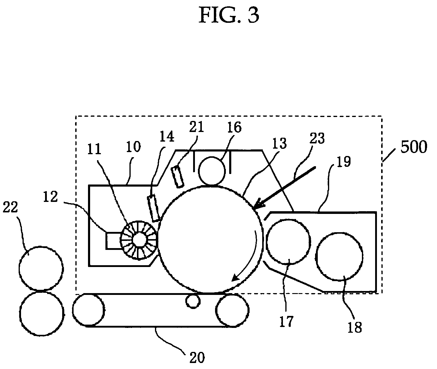
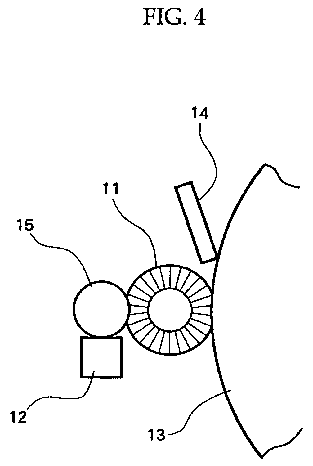
BACKGROUND OF THE INVENTION[0001]1. Field of the Invention[0002]The present invention relates to a photoconductor using laser light or other coherent light as a writing light, and to an image forming apparatus and a cartridge for an image forming apparatus using the photoconductor.[0003]2. Description of the Related Art[0004]An electrophotographic process by use of coherent light, such as laser light, as a writing light, is widely used for the formation of digital images such as in copying machines, printers and facsimile apparatus.[0005]In an electrophotographic process using coherent light as a writing light, an image including light and shade stripes (hereinafter referred to as interference fringes) is formed due to the interference of the coherent light within a photoconductive layer of the photoconductor. Such light and shade stripes are generated by the writing light being intensified when the photoconductor satisfies the relationship of 2nd=mλ wherein n is the refractive inde...
Claims
Application Information
Patent Timeline
Application Date:The date an application was filed.
Publication Date:The date a patent or application was officially published.
First Publication Date:The earliest publication date of a patent with the same application number.
Issue Date:Publication date of the patent grant document.
PCT Entry Date:The Entry date of PCT National Phase.
Estimated Expiry Date:The statutory expiry date of a patent right according to the Patent Law, and it is the longest term of protection that the patent right can achieve without the termination of the patent right due to other reasons(Term extension factor has been taken into account ).
Invalid Date:Actual expiry date is based on effective date or publication date of legal transaction data of invalid patent.

