
Image forming apparatus capable of changing operating state

Active Publication Date: 2013-05-23
KONICA MINOLTA BUSINESS TECH INC
View PDF10 Cites 51 Cited by
  • Summary
  • Abstract
  • Description
  • Claims
  • Application Information

AI Technical Summary

Benefits of technology

The patent aims to improve the reliability of power saving mode in an image forming apparatus. The technical effect is to enhance the reliability of the image forming apparatus during power saving mode.

Problems solved by technology

However, in the case where the human body detection signal of the human body sensor is used, there is a problem that the human body sensor is likely to falsely detect the human body to degrade reliability of the release of the power saving mode.
However, in this case, convenience is degraded for the user who wants to release the power saving mode as quickly as possible.
However, there is a problem that the low reliability of the release of the power saving mode remains in the technology of Document 1.
However, in the conventional technology, because the detection range is set irrespective of the angle of the manipulation panel, sometimes the human body of the person who has nothing to do with the manipulation of the image forming apparatus is falsely detected.

Method used


Image

  • Image forming apparatus capable of changing operating state
  • Image forming apparatus capable of changing operating state
  • Image forming apparatus capable of changing operating state

Examples


first modification

[First Modification]

[0097]In the above embodiment, only one human body detecting distance table is stored in ROM 12. The case where a plurality of human body detecting distance tables are stored in ROM 12 will be described in a first modification.

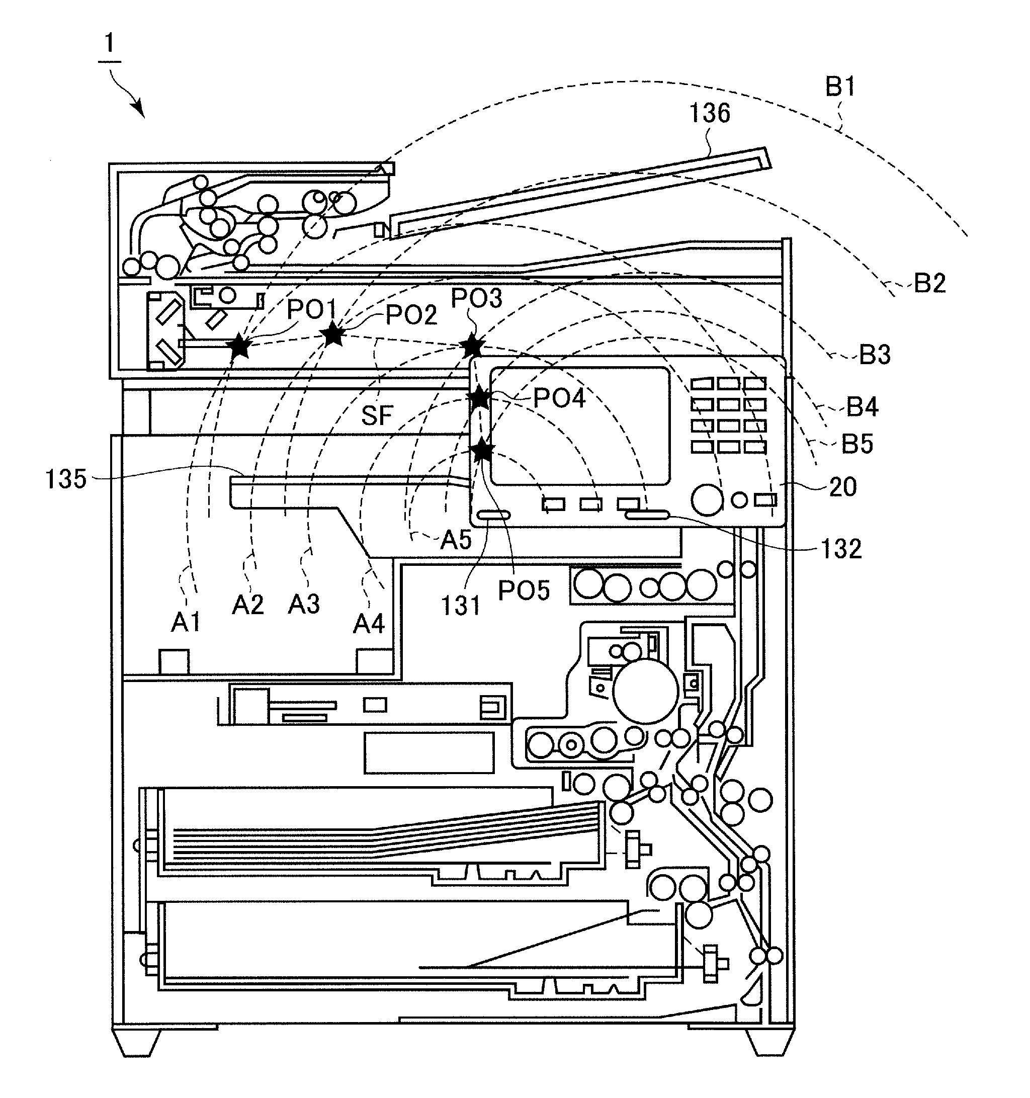
[0098]FIG. 13 is a view schematically illustrating a second human body detecting distance table.

[0099]Referring to FIG. 13, the second human body detecting distance table differs from the human body detecting distance table in FIG. 11 in that crossing point PO1 of boundary line A1 and boundary line B1, crossing point PO2 of boundary line A2 and boundary line B2, crossing point PO3 of boundary line A3 and boundary line B3, crossing point PO4 of boundary line A4 and boundary line B4, crossing point PO5 of boundary line A5 and boundary line B5, and crossing point PO6 of boundary line A6 and boundary line B6 are each located out of the detection range of sensor 23.

[0100]The human body detecting distance table in FIG. 11 and the human body detec...

second modification

[Second Modification]

[0102]In the above embodiment, antennas A and B detect the distance to the human body in the stepwise manner. The case where antennas A and B continuously detect the distance to the human body will be described in a second modification.

[0103]FIG. 14 is a view schematically illustrating a third human body detecting distance table.

[0104]Referring to FIG. 14, the third human body detecting distance table may be used in the case where antennas A and B continuously detect the distance to the human body. The third human body detecting distance table illustrates whether a combination of the range including the distance to the human body detected by antenna A and the range including the distance to the human body detected by antenna B falls within the detection range. The range of the distance detected by antenna A is divided into three ranges: a range of distances D1 and D2, a range of distances D2 and D3, and a range of distances D3 and D4. The range of distance detec...

third modification

[Third Modification]

[0106]The case where the detection range of sensor 23 is set based on the existence or non-existence of the output to the sheet discharge unit of copying machine 1 or the existence or non-existence of the placement of the authentication device in copying machine 1 will be described in a third modification.

[0107]FIG. 15 is a view schematically illustrating a relationship between sheet discharge unit 135 and the detectable ranges of antennas 131 and 132.

[0108]Referring to FIG. 15, copying machine 1 includes sheet discharge unit 135 that is disposed in the central portion thereof. The output (sheet on which the image is printed) is discharged from the main body of copying machine 1 to sheet discharge unit 135. Angle θ of manipulation panel 20 can be changed. FIG. 15 illustrates the state in which manipulation panel 20 is in the perpendicular state (angle θ of 90 degrees). Sensor 23 includes a plurality of rod-shaped antennas 131 and 132 that are disposed at position...


PUM


Abstract

An image forming apparatus can change an operating state between a normal mode and a power saving mode having power consumption lower than that of the normal mode. The image forming apparatus sets a detection range based on at least one of an angle of a manipulation panel, existence or non-existence of an output to the sheet discharge unit, and existence or non-existence of placement of the authentication device. The image forming apparatus detects an approach of a human body when the operating state is in the power saving mode. When a sensor detects that the human body approaches the detection range, the image forming apparatus returns the operating state from the power saving mode to the normal mode.

Description

[0001]This application is based on Japanese Patent Application No. 2011-253487 filed with the Japan Patent Office on Nov. 21, 2011, the entire content of which is hereby incorporated by reference.BACKGROUND OF THE INVENTION[0002]1. Field of the Invention[0003]The present invention relates to an image forming apparatus capable of changing an operating state, particularly to an image forming apparatus capable of changing an operating state between a normal mode and a power saving mode having power consumption lower than that of the normal mode.[0004]2. Description of the Background Art[0005]Examples of an electrophotographic image forming apparatus in which an image is formed by an electrophotographic system include an MFP (Multi Function Peripheral) having a scanner function, a facsimile function, a copying function, a function as a printer, a data communication function, and a server function, a facsimile machine, a copying machine, and a printer.[0006]In a general image forming pro...

Claims


Application Information

Patent Timeline
IPC IPC(8): G06K15/02
CPCG06K15/02H04N1/00323H04N1/00496H04N1/00912H04N2201/0094G03G15/5004Y02B60/1289G06K15/406H04N1/00896G06F1/3231G06F1/3284Y02B60/1267G06K15/005Y02D10/00
Inventor YAMADA, TOMOAKI
Owner KONICA MINOLTA BUSINESS TECH INC
Features
  • Generate Ideas
  • Intellectual Property
  • Life Sciences
  • Materials
  • Tech Scout
  • Unparalleled Data Quality
  • Higher Quality Content
  • 60% Fewer Hallucinations
Learn More