Image forming apparatus having reply mail generating function and method for controlling the same

a technology of image forming and mail generating function, which is applied in the field of image forming apparatus, can solve the problems of achieve the effect of eliminating mail selection errors in sending reply mails responding to original mails and small amount of mail information on printed documents

Inactive Publication Date: 2013-05-23
CANON KK
View PDF4 Cites 0 Cited by
  • Summary
  • Abstract
  • Description
  • Claims
  • Application Information

AI Technical Summary

Benefits of technology

[0041]According to exemplary embodiments of the present invention, a reply mail is generated by scanning a paper on which a Message-ID of an original mail is printed. Therefore, the amount of mail information on a printed document is small. Furthermore, the reply mail is generated by automatically identifying the original mail based on the read Message-ID. Therefore, mail selection errors in sending reply mails responding to original mails can be eliminated.

Problems solved by technology

Therefore, the amount of mail information on a printed document is small.

Method used


Image

  • Image forming apparatus having reply mail generating function and method for controlling the same
  • Image forming apparatus having reply mail generating function and method for controlling the same
  • Image forming apparatus having reply mail generating function and method for controlling the same

Examples


second exemplary embodiment

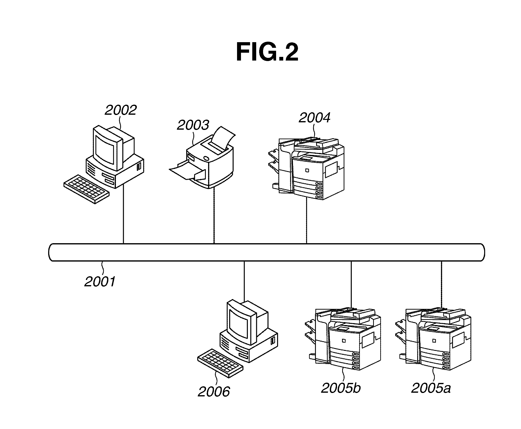
[0119]In an exemplary embodiment, the approver 7005 uses the multifunction peripheral 2005a to perform reception of mails and sending of reply mails. In another exemplary embodiment (second exemplary embodiment), the approver 7005 can use two or more multifunction peripherals.

[0120]FIG. 8 illustrates an example of mail sending operation screen 8000, which can be provided by the software configuration illustrated in FIG. 7 and displayed on the LCD unit 6001 of the operation unit 3050. The sending operation screen 8000 enables a user to instruct mail sending operations (see 7010, 7011, and 7012) in the application task workflow.

[0121]A function setting button 8001 enables a user to select the function of software. FIG. 8 illustrates a “Send” function currently selected. An address type switching button 8010 enables a user to select the type of mail address among “To”, “Cc”, and “Bcc.” The screen example illustrated in FIG. 8 is in a state where a user can designate an address in the “...

first exemplary embodiment

[0218]Compared to the first exemplary embodiment, a second exemplary embodiment allows the approver 7005 to use a plurality of multifunction peripherals.

[0219]According to the second exemplary embodiment, the approver 7005 may use one multifunction peripheral to receive an applicant's mail and print an application form and another multifunction peripheral to return an application form processed by the approver 7005 to the applicant 7001.

[0220]A business workflow system according to the second exemplary embodiment is similar to the business workflow system described in the first exemplary embodiment and is therefore not described below.

[0221]FIG. 24 illustrates an exemplary software configuration of a multifunction peripheral and a data storage unit according to the second exemplary embodiment, which is different in the following features from the configuration illustrated in FIG. 5.

[0222]A device mail processing control unit 5030, which can be loaded from the HDD 3004 in a system st...


PUM


Abstract

An image forming apparatus includes units, such as mail reception, mail management, reading, detection, device identifier comparing, retrieval, printing, and mail attaching and sending. The mail management unit stores received electronic mail. The detection unit detects electronic mail identification information and a device identifier contained in document image data generated from a document image. The detected device identifier is compared with the image forming apparatus device identifier. If the detected device identifier corresponds to the image forming apparatus device identifier, then the retrieval unit searches the stored electronic mail in the mail management unit for an electronic mail corresponding to the electronic mail identification information. The printing unit performs printing of the electronic mail stored in the mail management unit. If the detected device identifier does not correspond, an electronic mail containing the read document image data is sent to an image forming apparatus having the detected device identifier.

Description

CROSS REFERENCE TO RELATED APPLICATIONS[0001]The present application is a divisional of U.S. patent application Ser. No. 12 / 338,756, filed on Dec. 18, 2008, which claims priority from Japanese Patent Application No. 2007-328713, filed Dec. 20, 2007, all of which are hereby incorporated by reference herein in their entirety.BACKGROUND OF THE INVENTION[0002]1. Field of the Invention[0003]The present invention relates to an image forming apparatus configured to generate a mail replying to a received mail and a method for controlling the image forming apparatus.[0004]2. Description of the Related Art[0005]Popularization of personal computers (PCs) and network services (e.g., Internet and Intranet) enables many users to communicate with each other via electronic mails. There are various types of mail softwares (e.g., Microsoft Outlook Express provided by Microsoft Corporation) operable on PCs of users who send and receive information. Electronic mails capable of easily and quickly sendin...

Claims


Application Information

Patent Timeline
Patent Type & Authority Applications(United States)
IPC IPC(8): H04N1/00
CPCG06F3/1293H04L12/5835H04L51/066H04N1/00212H04N1/00222H04N1/00209H04N1/0036H04N1/00363H04N1/00366H04N1/00374H04N1/00355
Inventor FUJIKAWA, SHINJI
Owner CANON KK
Why Eureka
Try Eureka