
Downhole Communication System

a communication system and downhole technology, applied in the field of wireless telemetry systems, can solve the problems increased complexity of cable inside the tubing, and inability to obtain direct feedback from downhole tools

Inactive Publication Date: 2013-05-23
SCHLUMBERGER TECH CORP
View PDF7 Cites 37 Cited by
  • Summary
  • Abstract
  • Description
  • Claims
  • Application Information

AI Technical Summary

Benefits of technology

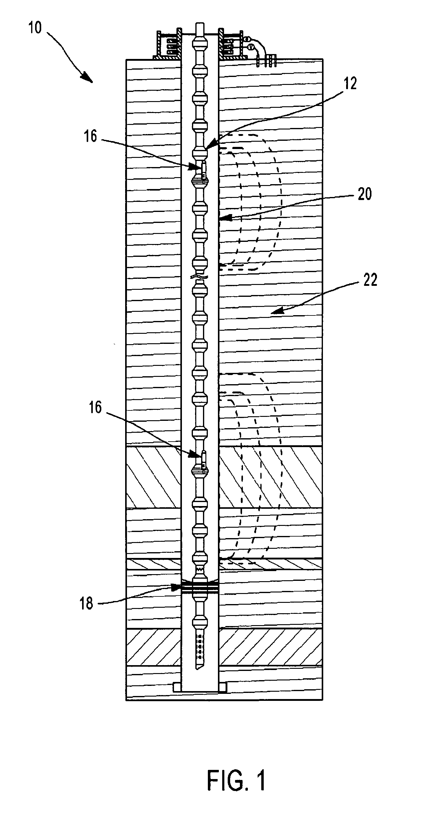
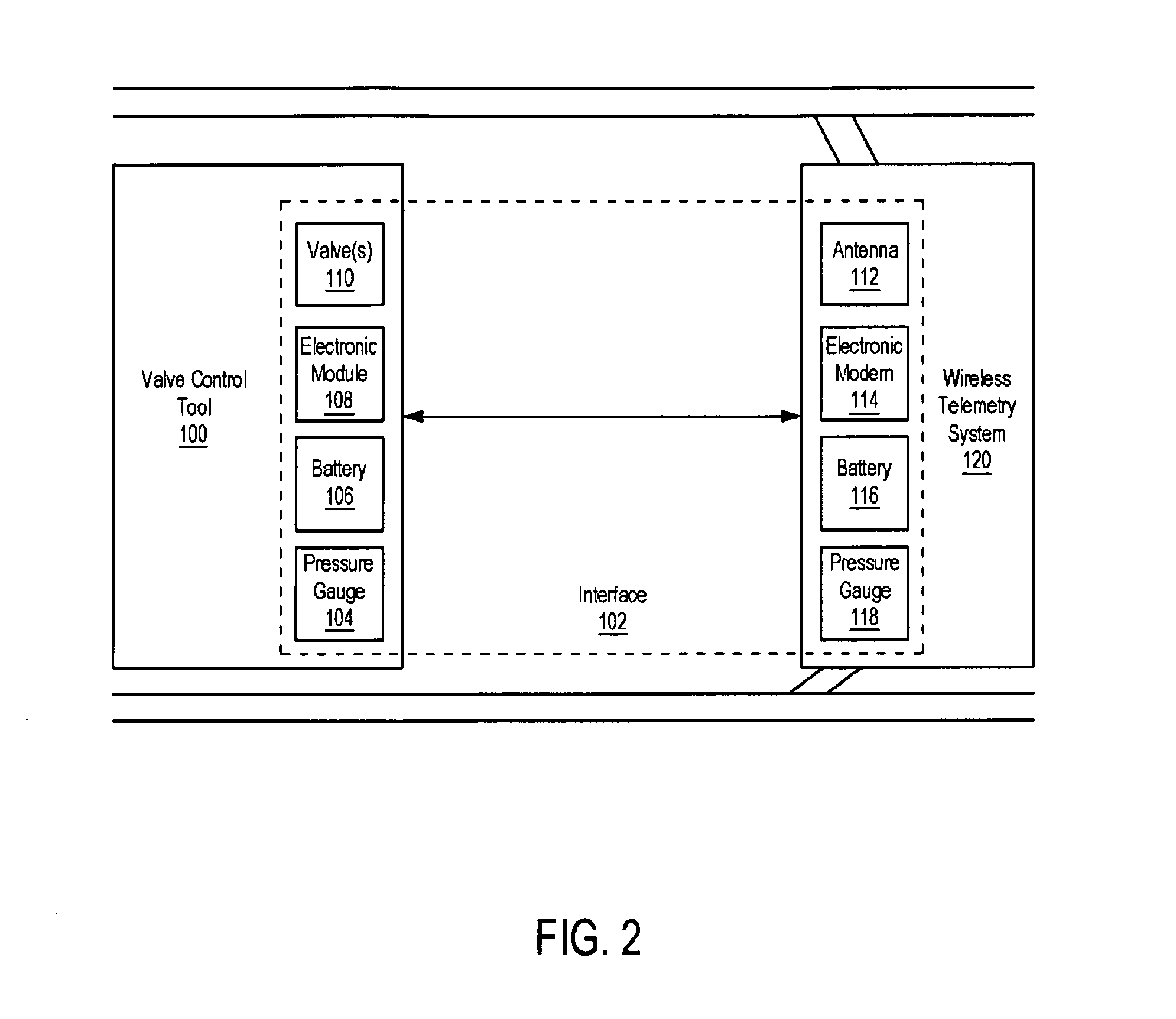
This patent discloses a system for communication between a downhole location and a surface location in a wellbore. The system includes a first and second telemetry modules, a downhole tool, and an interface for selectively relaying digital communication signals. The interface receives the communication signals via at least one of acoustic propagation, low frequency electromagnetic transmission, and fluid pressure pulse commands. The system allows for the efficient transfer of information between the downhole location and surface location in a wellbore.

Problems solved by technology

One of the more difficult problems associated with any borehole is to communicate measured data between one or more locations down a borehole and the surface, or between downhole locations themselves.
Similarly when operating some of the downhole testing tools from surface, such as tester valves, circulating valves, packer, samplers or perforating charges, the operators do not obtain a direct feedback from the downhole tools.
While much effort has been spent on “wireline” communication, its deployment can pose problems for some downhole operations since using a cable since inside the tubing string limits the flow diameter and requires complex structures to pass the cable from the inside to the outside of the tubing, and space outside the tubing is limited leaving a cable vulnerable to being damaged.
A cable inside the tubing is also an additional complexity in case of emergency disconnect for an offshore platform.
Each of these wireless communication systems provide certain benefits, and inherently comprise certain limitations.

Method used


Image

  • Downhole Communication System
  • Downhole Communication System
  • Downhole Communication System

Examples


Embodiment Construction

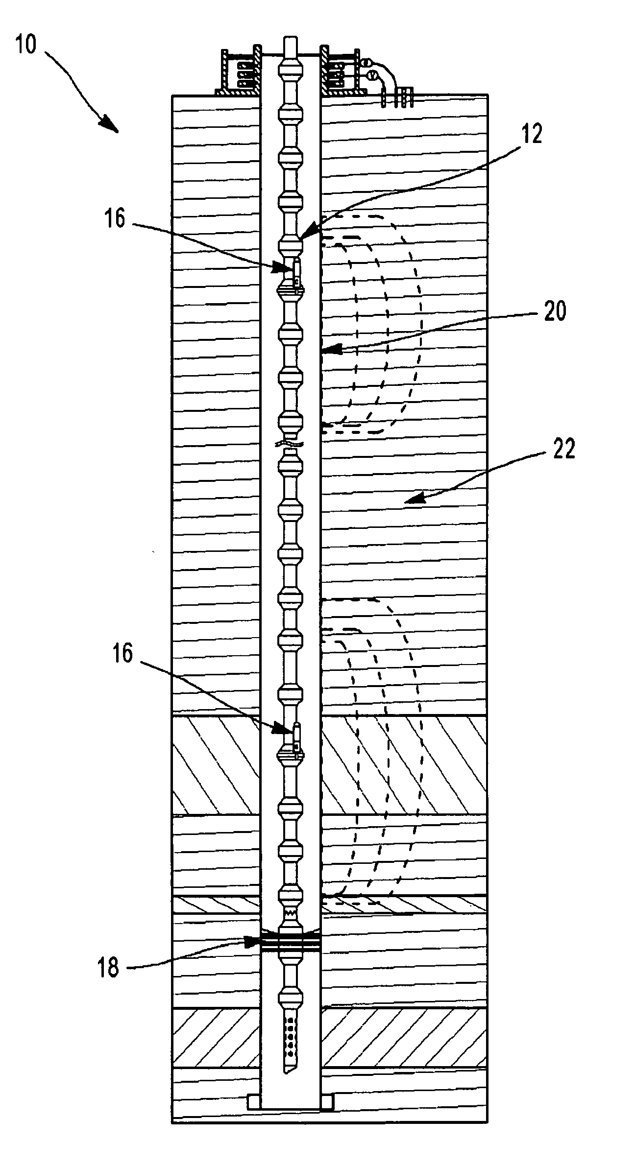
[0021]Specific embodiments of the present disclosure will now be described in detail with reference to the accompanying Figures. Like elements in the various Figures are denoted by like reference numerals for consistency.

[0022]In the following detailed description of embodiments of the present disclosure, numerous specific details are set forth in order to provide a more thorough understanding of the present disclosure. However, it will be apparent to one of ordinary skill in the art that the present disclosure may be practiced without these specific details. In other instances, well-known features have not been described in detail to avoid unnecessarily complicating the description.

[0023]In general, embodiments of the present disclosure provide methods and apparatuses for communicating between a location downhole and the surface, or between downhole locations themselves. More specifically, embodiments of the present disclosure relate to dual control of downhole testing and circulat...


PUM


Abstract

A downhole communication system and method is presented for communicating between a downhole location within a wellbore and a surface location. The system preferably comprises a first and second telemetry module, a downhole tool, and an interface electrically connecting the downhole tool to the first and second telemetry modules. The first telemetry module is connected to a string and positioned downhole within the wellbore, and configured to receive communication signals via acoustic propagation or low frequency electromagnetic transmission. The second telemetry module is connected to the string and positioned downhole within the wellbore, and configured to receive communication signals via fluid pressure pulse commands. The downhole tool is operatively connected to the string. And the interface is adapted to selectively relay digital communication signals between the downhole tool and at least one of the first and second telemetry modules.

Description

CROSS-REFERENCE TO RELATED APPLICATION[0001]The present application is based on and claims priority to U.S. Provisional Patent Application No. 61 / 290,328, entitled “DUAL DOWNHOLE COMMUNICATION SYSTEM,” filed Dec. 28, 2009.TECHNICAL FIELD[0002]The present disclosure relates, in general, to wireless telemetry systems for use with installations in oil and gas wells or the like. More particularly, but not by way of limitation, the present disclosure relates to a downhole communication system and apparatus for bi-directional communication between a location down a borehole and the surface, or between downhole locations themselves.BACKGROUND[0003]One of the more difficult problems associated with any borehole is to communicate measured data between one or more locations down a borehole and the surface, or between downhole locations themselves. For example, in the oil and gas industry it is desirable to communicate data generated downhole to the surface during operations such as drilling, ...

Claims


Application Information

Patent Timeline
Patent Type & Authority Applications(United States)
IPC IPC(8): G01V3/18
CPCE21B17/028E21B47/12G01V3/18E21B47/18G01V11/002E21B47/122E21B47/13
Inventor CONTANT, MATTHELEMENAGER, ERWANNMERLAU, DAVIDMOHAN, AMIT
Owner SCHLUMBERGER TECH CORP
Learn More