Multi-layer network diagnostic tracing

a network diagnostic and multi-layer technology, applied in the field of multi-layer network diagnostic tracing, can solve the problems of network users experiencing service disruption, and the icmp cannot determine which bridge is dropping packets

Active Publication Date: 2013-05-23
EXTREME NETWORKS INC
View PDF9 Cites 44 Cited by
  • Summary
  • Abstract
  • Description
  • Claims
  • Application Information

AI Technical Summary

Benefits of technology

[0007]CFM based troubleshooting can determine which bridge among the set of bridges between a pair of router is dropping the traffic. However, CFM based tools require the users to specify MAC addresses as command line arguments. This is fairly

Problems solved by technology

The monitoring application therefore interfaces with users via layer 3 identifiers, which are often less cumbersome and readily identifiable by inspection than their L2 counterparts, however performs continuity diagnostics such as ping and traceroute operations using L2 identifiers, therefore pinpointing problems with an L2 network forwarding entity such as a bridge that lies between L3 entities such as routers.
When network devices

Method used


Image

  • Multi-layer network diagnostic tracing
  • Multi-layer network diagnostic tracing
  • Multi-layer network diagnostic tracing

Examples


Embodiment Construction

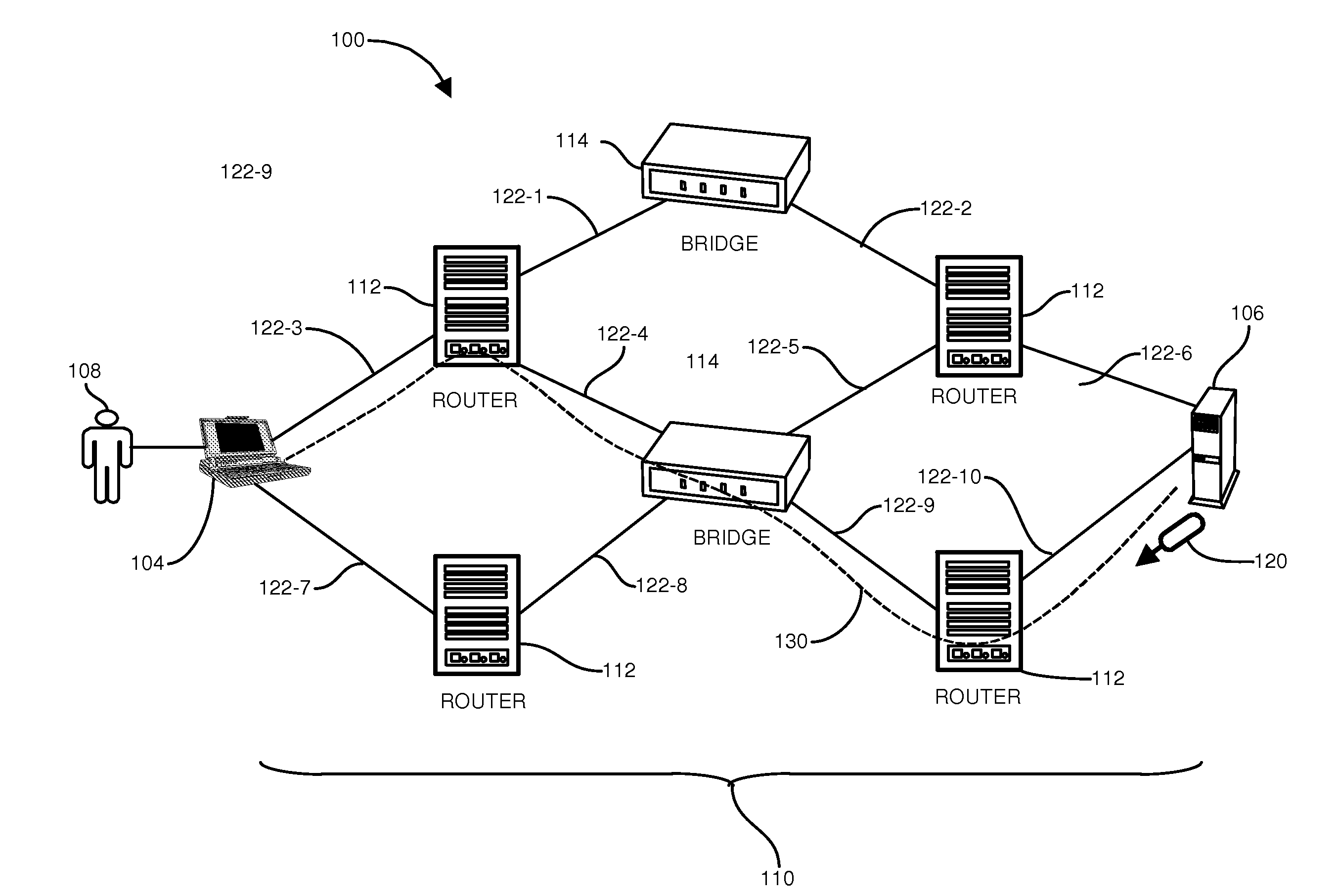
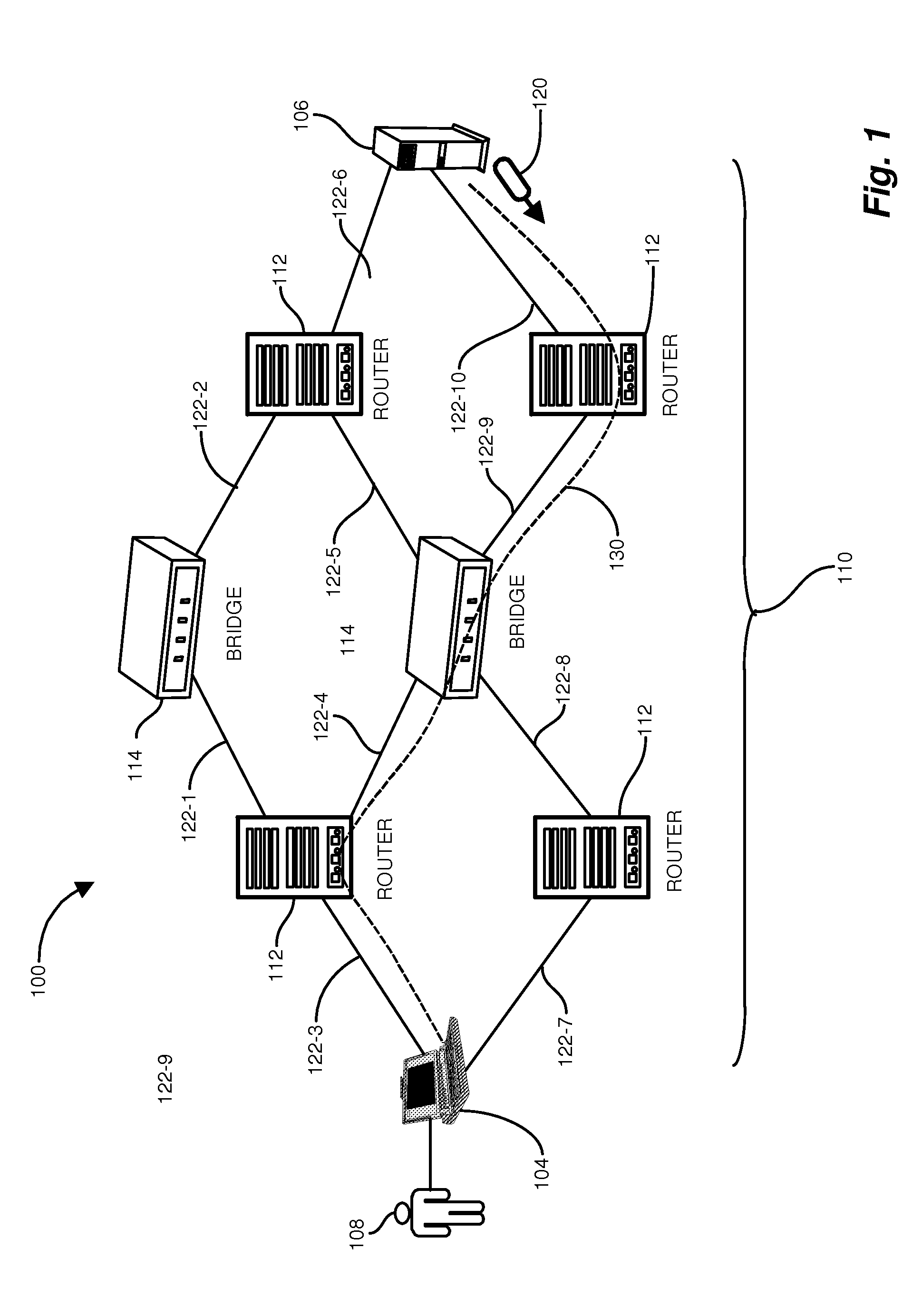
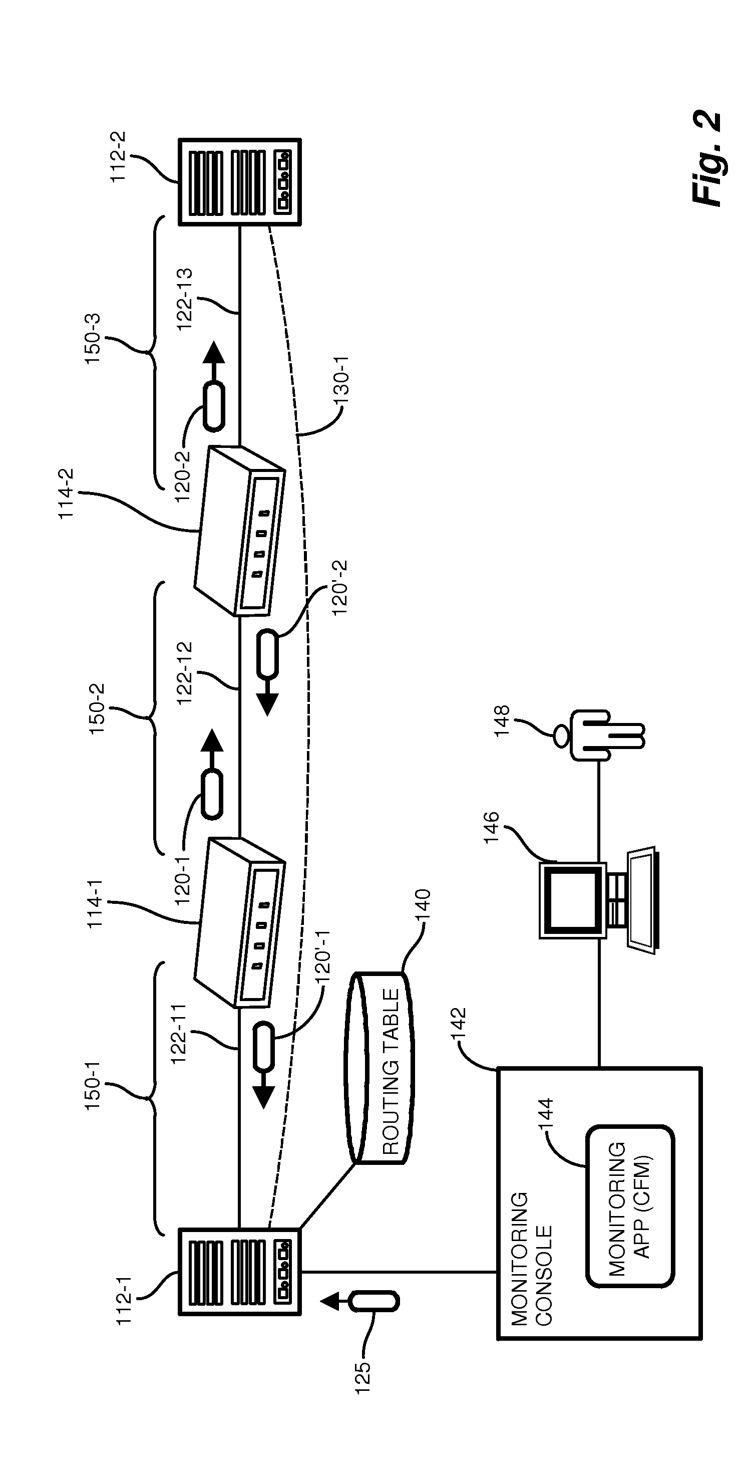
[0014]Depicted below is an example configuration of a networking environment suitable for use with configurations disclosed herein. An example network such as an SPBM network employs a monitoring application responsive to a network operator for issuing diagnostic commands that result in diagnostic messages sent by the monitoring application to network entities (forwarding entities) on a path for which diagnostic continuity information is sought. In contrast to conventional approaches, which require specific interrogation of L2 entities using cryptic L2 (MAC) labels, configurations herein receive L3 identifiers such as IP addresses, allowing a more intuitive and less error prone user invocation.

[0015]Conventional approaches require an operator to enter MAC addresses on command line parameters, often requiring manual mapping of network entities and is often a tedious process. Other conventional approaches include tracing the Layer-2 identifier to an IP address—which takes source and d...


PUM


Abstract

A network management and monitoring application employs diagnostic messages for confirming network path connectivity and identifying and locating connectivity faults. Diagnostic messages similar to conventional “ping” and “traceroute” messages traverse the network along a prescribed path for which diagnostic feedback is desired. The application receives and analyzes return messages sent from network entities along the path to ascertain connectivity issues on the path. The application receives layer 3 identifiers such as IP addresses, however performs diagnostic operations such as continuity checks based on layer 2 identifiers such as MAC (Media Access Control) identifiers because certain network entities operate on L2 identifiers and would otherwise evade a continuity check based on layer 3 identifiers. The monitoring application therefore performs continuity diagnostics such as ping and traceroute operations using L2 identifiers, therefore pinpointing problems with an L2 network forwarding entity such as a bridge that lies between L3 entities such as routers.

Description

BACKGROUND[0001]Modern computer networks strive for transparency of the physical network. Various utilities and applications are available for providing a user with a similar login experience regardless of location, enabling trends such as telecommuting and virtual private networks (VPNs). In a Virtual Local Area Network (VLAN), for example, users in distinct physical networks employ transport services that appear to be part of the same LAN. The IEEE 802.1aq standard of Shortest Path Bridging (SPB) networks extends the well entrenched Ethernet approach for accommodating virtual LANs and wireless transport. Multiple paths coexist such that a shortest path with minimal latency is automatically created and if there is a failure of a link or switch, the failover time is minimal. SPB also removes the complexity of manual VLAN extensions and avoids the somewhat cumbersome spanning tree protocol.[0002]In an SPBM network, mechanisms are employed to debug connectivity issues and to isolate f...

Claims


Application Information

Patent Timeline
IPC IPC(8): H04L12/26
CPCH04L43/0811H04L45/70H04L41/0677H04L43/10
Inventor KEESARA, SRIKANTHFRATTURA, DAVID E.FITZGERALD, DEBORAH E.MONTI, CHRISTOPHER
Owner EXTREME NETWORKS INC
Why Eureka
Try Eureka