Optical cable

a technology of optical fibers and optical fiber ribbons, applied in the field of optical cables, can solve the problems of increasing the transmission loss of each optical fiber, and reducing the flexibility of the optical fiber, so as to facilitate the identification of optical fibers and improve workability

Inactive Publication Date: 2013-05-23
SUMITOMO ELECTRIC IND LTD
View PDF1 Cites 12 Cited by
  • Summary
  • Abstract
  • Description
  • Claims
  • Application Information

AI Technical Summary

Benefits of technology

[0010]In the optical cable disclosed in Japanese Utility Model Application Laid-Open No. 62-46414, a plurality of optical fiber ribbons are stacked and bonded together, so that optical fibers contained in one optical fiber ribbon do not intersect with optical fibers contained in another optical fiber ribbon. However, an optical cable having a structure in which a plurality of optical fiber ribbons are stacked and bonded together reduces its flexibility and thus is hard to bend at a small radius, which lowers its workability at the time of being laid out. When the optical cable is bent forcibly, optical fiber ribbons therewithin may be bent compulsorily, so as to increase transmission loss in optical fibers contained in the optical fiber ribbons.
[0025]In the optical cable, each of the plurality of optical fibers may include a core and a cladding surrounding the core, the core and cladding being constituted by glass and a plastic, respectively. The plurality of optical fibers may further include a color layer arranged on an outer periphery of the cladding. This makes it easier to identify an optical fiber to be processed at a terminal of the optical cable, thereby improving the workability.

Problems solved by technology

When a lateral pressure is applied to an intersection between optical fibers in such an optical cable containing a plurality of optical fibers in a relatively thin sheath, transmission loss may increase in each optical fiber.
When a lateral pressure is applied to an intersection between optical fiber ribbons contained in a tube, transmission loss may also increase in optical fibers contained in each optical fiber ribbon.
However, an optical cable having a structure in which a plurality of optical fiber ribbons are stacked and bonded together reduces its flexibility and thus is hard to bend at a small radius, which lowers its workability at the time of being laid out.

Method used


Image

  • Optical cable
  • Optical cable
  • Optical cable

Examples


first embodiment

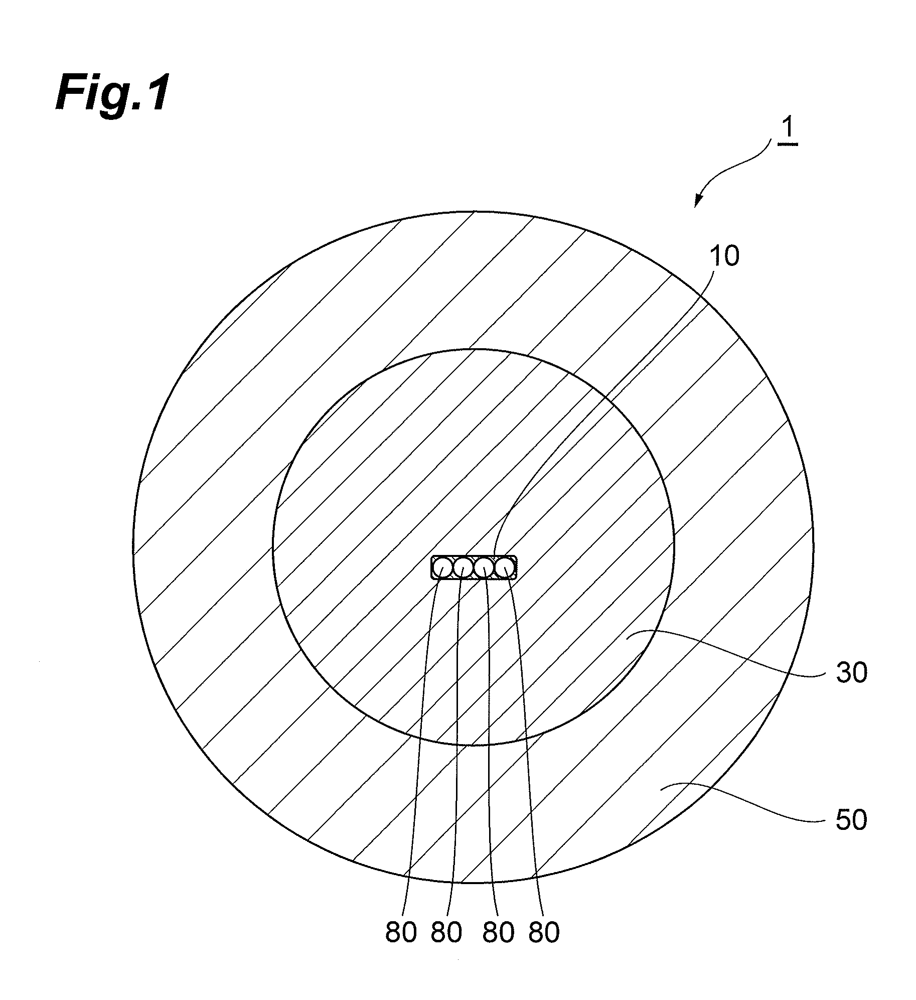
[0044]FIG. 1 is a sectional view of an optical cable 1 in accordance with the first embodiment. FIG. 1 illustrates a cross section perpendicular to the central axis of the optical cable 1. The optical cable 1 comprises an optical fiber ribbon 10, a tension member 30, and a sheath 50.

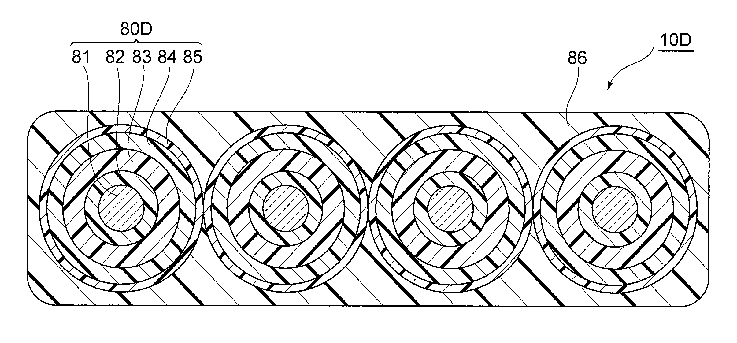
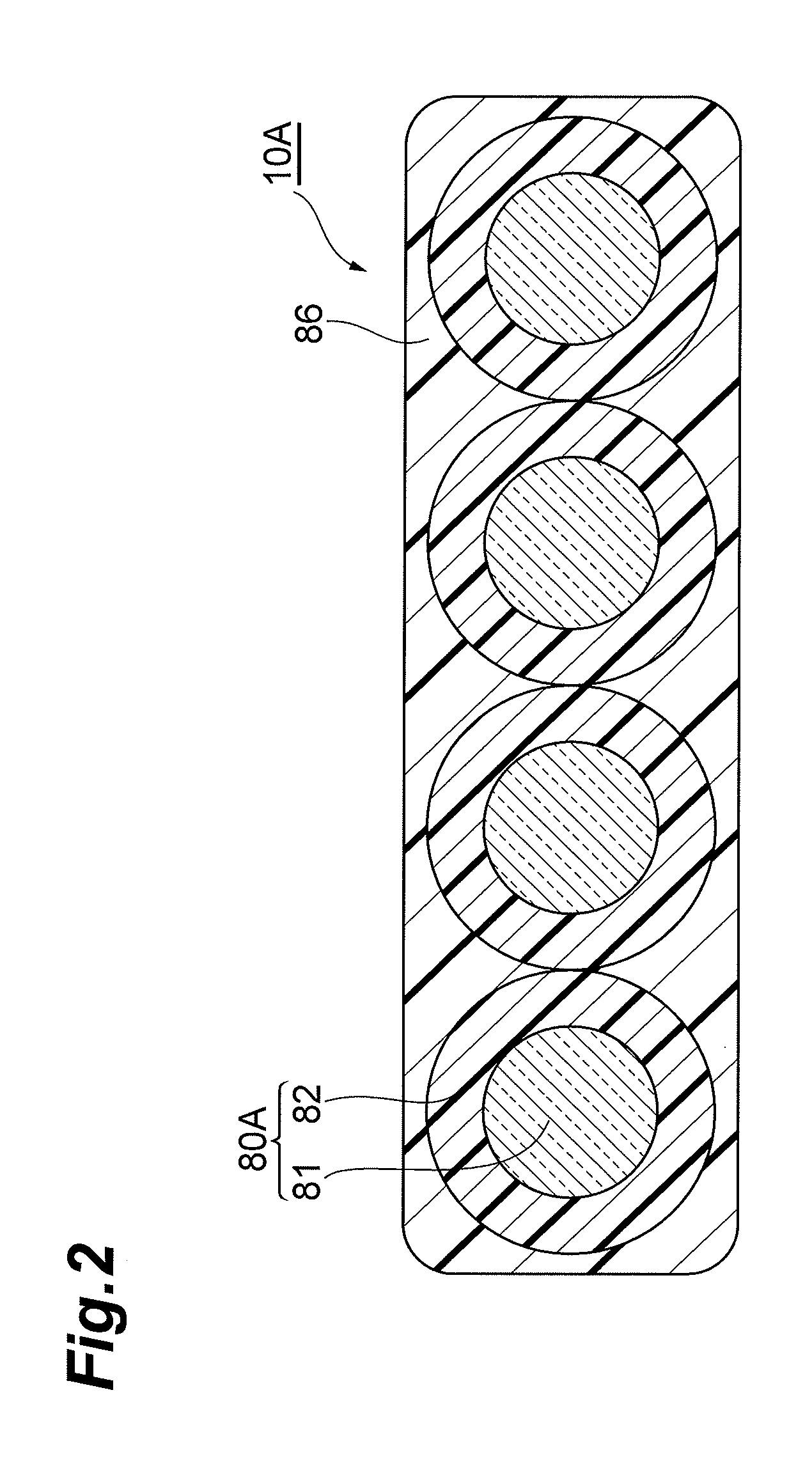
[0045]The optical fiber ribbon 10 is constructed by integrating a plurality of optical fibers 80 arranged in parallel. In general, the plurality of optical fibers 80 are an even number of optical fibers. The sheath 50 is provided so as to surround the optical fiber ribbon 10. The sheath 50 is used for protecting the optical cable 1 and constituted by a polyolefin, examples of which include PVC, PE, and EVA. One optical fiber ribbon 10 is twistably arranged within an inner space surrounded by the sheath 50.

[0046]The tension member 30 may be disposed about the optical fiber ribbon 10. The tension member 30, which is preferably fibrous, is preferably made of an aramid fiber (Kevlar (registered trademark)). ...

second embodiment

[0059]FIG. 6 is a sectional view of an optical cable 2 in accordance with the second embodiment. FIG. 6 illustrates a cross section perpendicular to the central axis of the optical cable 2. The optical cable 2 comprises a optical fiber ribbon 10, an inner tube 20, a tension member 30, an electromagnetic shield layer 40, and an sheath 50.

[0060]The optical fiber ribbon 10 is inserted in an inner space 21 of the inner tube 20 and twistable in the inner space 21. One optical fiber ribbon 10 is inserted in the inner space 21 of the inner tube 20, which is constituted by polyvinyl chloride (PVC), for example. The inner space 21 of the inner tube 20 has such a size that the optical fiber ribbon 10 is twistable therein. Preferably, the diameter of the inner space 21 of the inner tube 20 is greater than the width (in the direction in which the plurality of optical fibers are arranged) of the optical fiber ribbon 10 by at least 0.2 mm. The inner tube 20 having a thickness of 0.3 to 1 mm, for ...

third embodiment

[0065]FIG. 7 is a sectional view of an optical cable 3 in accordance with the third embodiment. FIG. 7 illustrates a cross section perpendicular to the central axis of the optical cable 3. The optical cable 3 comprises an optical fiber ribbon 10, an inner tube 20, a tension member 30, an electromagnetic shield layer 40, and a sheath 50 and, in addition, wires 61 and fillers 70. The third embodiment differs from the second embodiment in that the wires 61 and fillers 70 having the same outer diameter are disposed on the outside of the inner tube 20 but inside of the electromagnetic shield layer 40. While nine wires 61 and four fillers 70 are provided in FIG. 7, their numbers are arbitrary. All of those arranged on the outside of the inner tube 20 may be constituted by wires and no fillers. Two wires may form a pair. Each of the wires 61, which is a metal wire surrounded with an insulating coating or a coaxial electronic wire, can propagate electric signals. The tension member 30 is di...


PUM


Abstract

An optical cable comprises an optical fiber ribbon, a tension member and a sheath. The optical fiber ribbon is constructed by integrating a plurality of optical fibers arranged in parallel. The sheath is provided so as to surround the optical fiber ribbon. The sheath is used for protecting the optical cable. One optical fiber ribbon is arranged twistably within an inner space surrounded by the sheath.

Description

BACKGROUND OF THE INVENTION[0001]1. Field of the Invention[0002]The present invention relates to an optical cable.[0003]2. Related Background Art[0004]Japanese Utility Model Application Laid-Open No. 60-165918 discloses a reinforcement-plastic-coated loose tube cable. This loose tube cable has a structure in which one or a plurality of coated optical fibers are contained in a tube made of a thermoplastic resin. The plurality of coated optical fibers are contained loosely in the tube without coming into close contact therewith.[0005]Japanese Utility Model Application Laid-Open No. 62-46414 discloses an optical fiber unit. This optical fiber unit has a structure in which a plurality of ribbon-shaped coated optical fibers are contained in a space within a cylindrical tube. The plurality of ribbon-shaped coated optical fibers are stacked on top of another and integrated on one side face thereof as being bonded to a tape through an adhesive.[0006]Japanese Patent Application Laid-Open No....

Claims


Application Information

Patent Timeline
Patent Type & Authority Applications(United States)
IPC IPC(8): G02B6/44
CPCG02B6/4401G02B6/443G02B6/4416G02B6/4403
Inventor HOMMA, YUYASAKABE, ITARUSOHMA, KAZUYUKI
Owner SUMITOMO ELECTRIC IND LTD
Why Eureka
Try Eureka