Composite Propeller Spar

a propeller blade and composite technology, applied in the field of blades and composite propeller blades, can solve the problems of reducing the useful life of the propeller, and affecting the operation of the machine/engin

Active Publication Date: 2013-05-23
THE BOEING CO
View PDF19 Cites 10 Cited by
  • Summary
  • Abstract
  • Description
  • Claims
  • Application Information

AI Technical Summary

Problems solved by technology

The characteristics of composite materials that provide lighter, stronger and stiffer structures, however, may include additional challenges.
For example, connecting a blade to a hub shaped assembly for a propeller with fasteners may provide challenges.
In this regard

Method used


Image

  • Composite Propeller Spar
  • Composite Propeller Spar
  • Composite Propeller Spar

Examples


Embodiment Construction

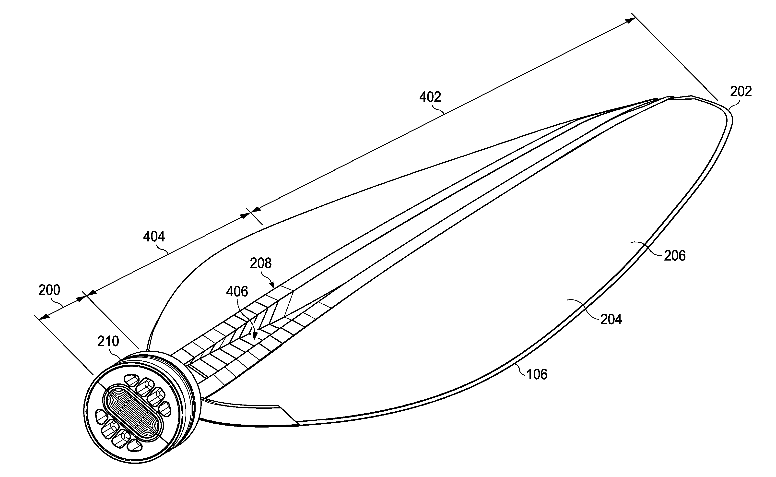
[0041]The different embodiments recognize and take into account that depending on the design, any time holes are drilled in a composite structure to add fasteners, stress at those points may be greater than desired. The different embodiments further recognize and take into account that the loads and vibrations that may occur on the blade at the location of the holes may increase a possibility that inconsistencies may occur over time.

[0042]The different embodiments recognize and take into account that one solution may be to bond the blade to a retention unit that holds the blade to a hub shaped assembly.

[0043]The different embodiments also recognize and take into account that the retention unit may include a structure that may fit inside of the blade in a manner that reduces the number of fasteners needed. The different embodiments, however, recognize and take into account that even with reducing the number of fasteners, any drilling of holes in a composite blade may be undesirable.

[...


PUM

PropertyMeasurementUnit
Thicknessaaaaaaaaaa
Lengthaaaaaaaaaa
Shapeaaaaaaaaaa

Abstract

A method and apparatus comprising a composite spar. The composite spar has a root section and a main section. The root section is closed and has a shape configured to be connected to a blade retention system. The main section has an open channel. The composite spar is configured for placement inside of a blade.

Description

BACKGROUND INFORMATION[0001]1. Field[0002]The present disclosure relates generally to vehicles and, in particular, to blades used on vehicles. Still more particularly, the present disclosure relates to composite propeller blades.[0003]2. Background[0004]A propeller is a mechanical structure that converts rotational motion into thrust. With a propeller, a pressure difference may be produced between the forward and rear surfaces of an airfoil-shaped blade. As a result, a fluid in which the propeller is located may be accelerated behind the blade. This fluid may be air or water.[0005]With aircraft, the propellers convert rotary motion generated by aircraft engines to provide the force to move the aircraft. Propellers may be made of many different types of materials. Propellers have been made from materials, such as wood and metal. Current propellers may employ composite materials. When blades for a propeller are made from composite materials, the propeller may be lighter, stronger, and...

Claims


Application Information

Patent Timeline
IPC IPC(8): F01D5/14F01D5/28B23P15/04F01D5/30
CPCY10T29/49337B64C11/26
Inventor MOSELAGE, III, JOHN HENRY
Owner THE BOEING CO
Why Eureka
Try Eureka