Combined propeller blade structure

A compound and blade technology, applied in the direction of rotating propellers, rotating propellers, etc., can solve the problems of performance bottlenecks and no further significant improvement, and achieve the effects of improving performance, easy implementation, and low cost

Inactive Publication Date: 2015-02-11
APPLIED THERMAL FLUID ANALYSIS CENT LIMITED LIABILITY
View PDF8 Cites 2 Cited by
  • Summary
  • Abstract
  • Description
  • Claims
  • Application Information

AI Technical Summary

Problems solved by technology

The existing technology is to adjust the size and angle of the fan blade to obtain the maximum performance. However, the obtained performance has reached the bottleneck and there is no further significant improvement.

Method used


Image

  • Combined propeller blade structure
  • Combined propeller blade structure
  • Combined propeller blade structure

Examples


Embodiment Construction

[0019] The detailed description of the present invention is described in the following, and the preferred embodiments described here are used for the purpose of illustration and description, and are not intended to limit the scope of the present invention.

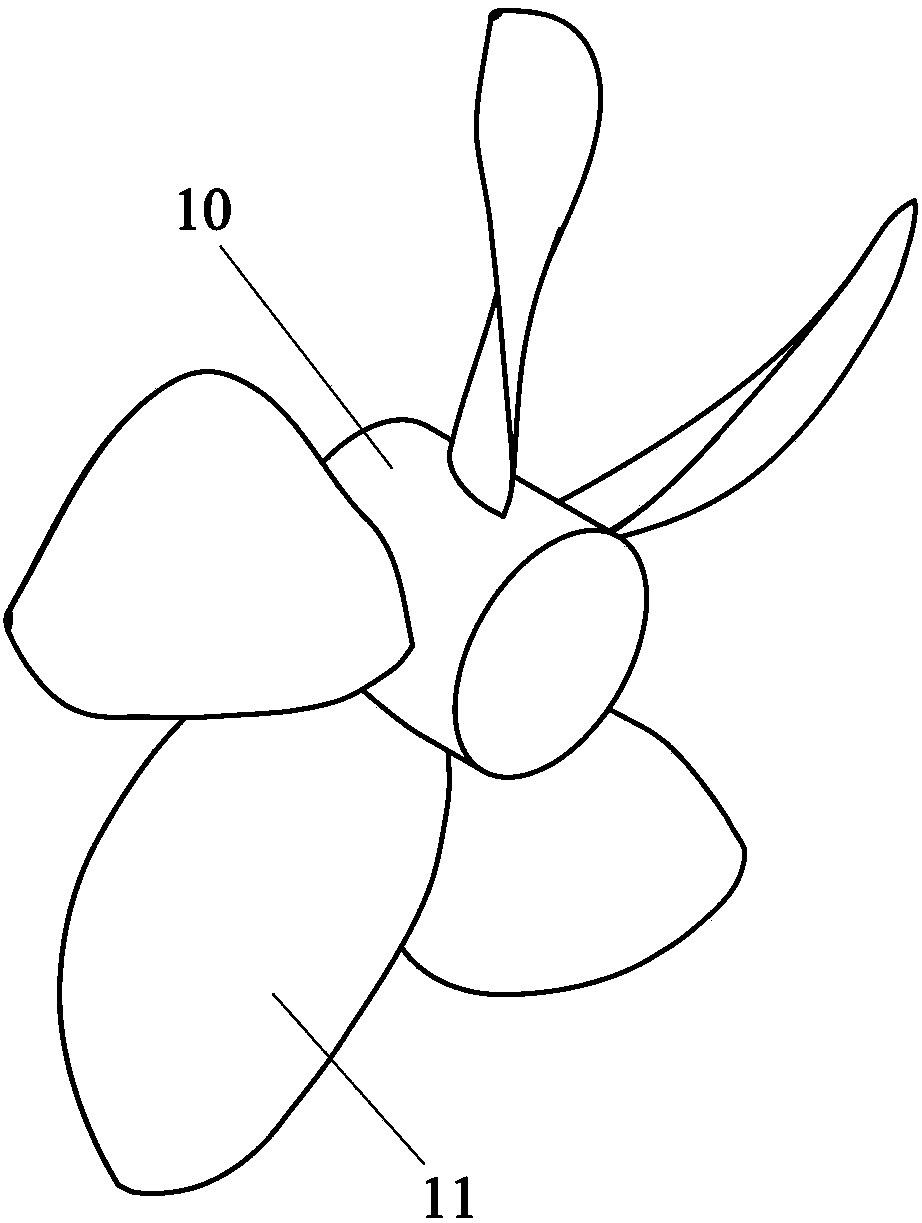
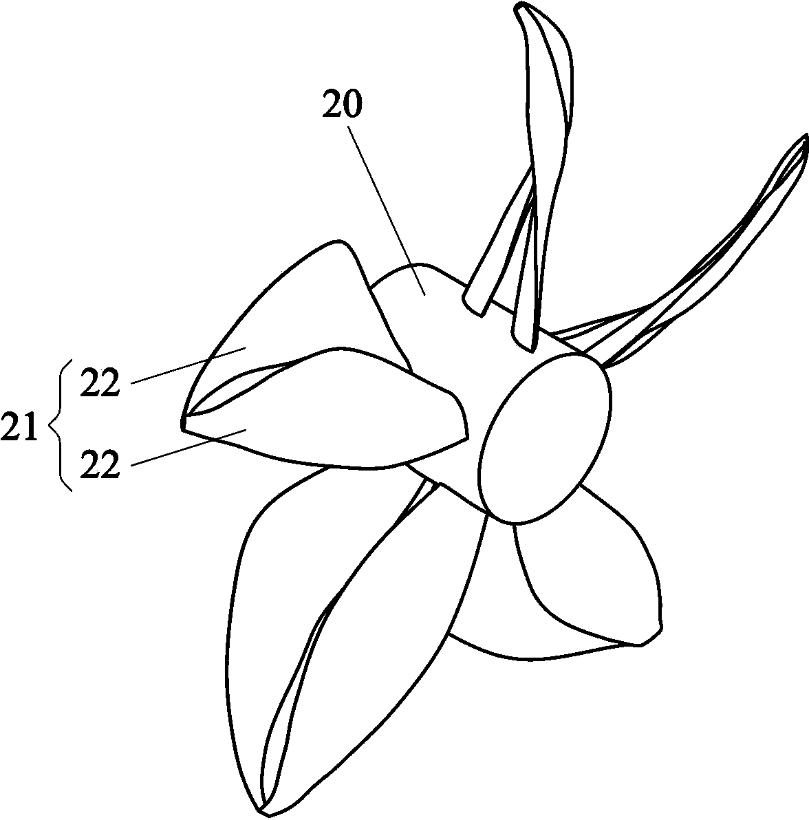
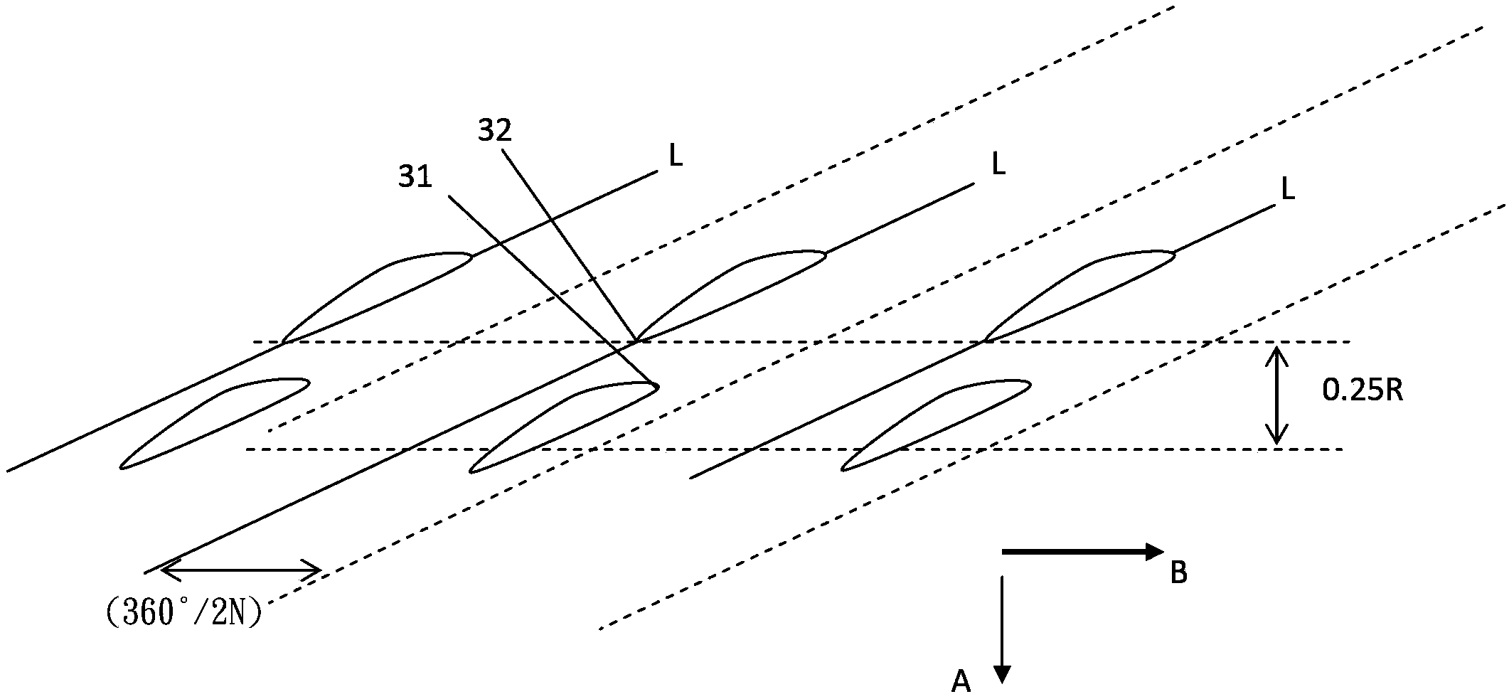
[0020] The present invention discloses a composite propeller blade structure, which is provided with at least one rotating shaft and a rotating side surface corresponding to the rotating shaft, and a plurality of fan blades are arranged on the rotating side surface, and the feature is: each of the aforementioned fan blades It is composed of a plurality of blade units, wherein the distance between any two adjacent blade units is greater than the distance between any adjacent two blade units, and the suction side of the blade unit on the downstream side is located at the pressure of the blade unit on the upstream side. side (Pressure Side); and in any of the equal radius sections of the aforementioned fan blades, the setting ...


PUM


Abstract

A composite propeller blade structure includes at least a rotation shaft and a rotation surface on which plural blades are formed, and characterized in that: each of the blades is composed of plural blade units; and in the equivalent radius cross section of each of the blades, the installed location of a front edge of the blade unit at the downstream is defined as following: in the rotation axial direction, which is located behind a rear edge of the adjacent blade unit at the upstream, and the maximum distance thereof is not greater than 25% of the radius of the adjacent blade unit at the upstream; and in the circumferential direction, located at the pressure surface side defined on the nose-trail line of the adjacent blade unit at the upstream, and the maximum range thereof is not greater than (360° / 2N), wherein N is the quantity of the blades.

Description

technical field [0001] The invention relates to a propeller blade structure for working in liquid fluid, in particular to a composite propeller blade structure. Background technique [0002] The propeller blade structure is an important equipment for human industry, including propellers of ships and submarines, which are generally driven by the propeller blade structure. Therefore, improving the efficiency of the propeller blade structure is very important for cost control, work efficiency or energy saving. [0003] A typical propeller blade structure must have at least one rotating shaft and a rotating side corresponding to the rotating shaft, and a plurality of identical fan blades are arranged on the rotating side. The existing technology is to adjust the size and angle of the fan blade to obtain the maximum performance, but the obtained performance has reached the bottleneck and there is no further significant improvement. [0004] Therefore, the present invention prop...

Claims


Application Information

Patent Timeline
Patent Type & Authority Applications(China)
IPC IPC(8): B63H1/14B63H1/26
CPCB63H1/26B63H1/265
Inventor 曾翌维
Owner APPLIED THERMAL FLUID ANALYSIS CENT LIMITED LIABILITY
Why Eureka
Try Eureka