Composite propeller blade of propeller

A technology of composite materials and propellers, which is applied in propellers, aircraft parts, transportation and packaging, etc., can solve the problems of poor bearing capacity, poor consistency, and prone to defects of propeller blades, and achieve good reliability and safety, and are not easy to dense voids , Excellent bearing effect

Pending Publication Date: 2021-03-02
AVIC HUIYANG AVIATION PROPELLER
View PDF0 Cites 1 Cited by
  • Summary
  • Abstract
  • Description
  • Claims
  • Application Information

AI Technical Summary

Problems solved by technology

[0002] Existing propeller composite material blades are composed of metal petioles and composite materials wrapped outside the metal petioles. The skins are all wrapped with carbon beams and metal blade roots. There is no foam filling and carbon fiber cloth inside the skin. The shape of the blade root is The aerodynamic performance is low, there are many layers on the metal blade root, the workmanship is poor, and defects are prone to occur, and the weight of the blade is heavy
The connection between the petiole and the foam core is V-shaped, the connection between the foam core and the petiole is weak, it is not easy to locate, and the carbon beam layup is not ideal, resulting in poor consistency of the blade after molding, and poor bearing capacity of the blade
Propeller blades require good aerodynamic performance, good structural reliability and safety, light weight, good design manufacturability, low scrap rate, etc. Existing composite material blades cannot meet these requirements

Method used


Image

  • Composite propeller blade of propeller
  • Composite propeller blade of propeller
  • Composite propeller blade of propeller

Examples


Embodiment Construction

[0025] The present invention will be further described below in conjunction with the accompanying drawings and specific embodiments.

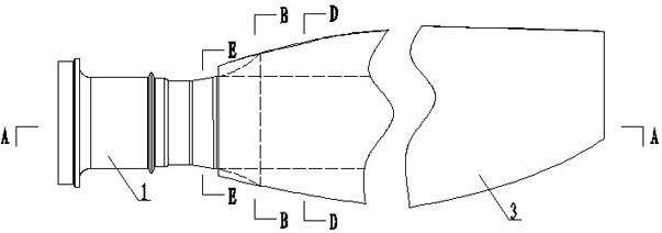
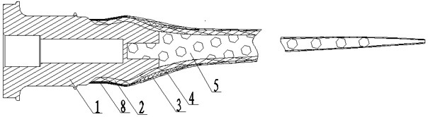
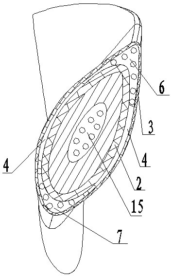
[0026] like Figure 1 to Figure 8 As shown, this embodiment includes a metal blade root 1 and a blade hull. The oar body includes foam core 5, carbon beam 2, front and rear edge filling foam 7, 6, carbon fiber cloth 4, carbon beam winding belt 8 and skin 3. The large end of the metal propeller root 1 is a structure connected to the propeller hoop. In this embodiment, there are 5 cylindrical sections; the small end starts from the back of the end cylinder of the large end, followed by the circular platform I16 with reduced diameter, and the smallest diameter with the circular platform I16. Cylinder I11 with the same diameter, circular platform II13 with larger diameter, transition cylinder II14 with the same large diameter as circular platform II13, and curved surface 17 consistent with the curved surface of the paddle body. The end cylinder o...


PUM

PropertyMeasurementUnit
diameteraaaaaaaaaa
lengthaaaaaaaaaa
lengthaaaaaaaaaa

Abstract

The invention discloses a composite propeller blade of a propeller. A circular truncated cone I, a cylinder I, a circular truncated cone II, a transition cylinder II and a curved surface consistent with a propeller body molded surface in bending are sequentially arranged at the small end of a metal propeller root from the back of a tail end cylinder of a large end; an oval end protruding from thecenter of the large end of the foam core matched with the bent shape of the propeller body is inserted into an oval groove in the center of the small end of the metal propeller root; the starting endsof the carbon beams are tightly attached to and wrap the circular truncated cone I, become two parts from the curved surface and are laid along rectangular grooves in the working surface and the non-working surface of the foam core; the skin wraps the curved surface of the metal propeller root and all parts of the propeller body from the transition cylinder II; the front edge filling foam and therear edge filling foam are filled in front edge and rear edge gaps between the skin and the metal propeller root; and the carbon fiber cloth is filled in the skin, the carbon beam and the foam core and all gaps among the skin, the carbon beam and the foam core, and the carbon beam winding belt is wound on the carbon beam portion without skin wrapping. The composite propeller blade disclosed by the invention is light in weight, reliable in structure, excellent in aerodynamic performance and good in paddle root fatigue resistance.

Description

technical field [0001] The invention relates to a propeller composite material blade. Background technique [0002] Existing propeller composite material blades are composed of metal petioles and composite materials wrapped outside the metal petioles. The skins are all wrapped with carbon beams and metal blade roots. There is no foam filling and carbon fiber cloth inside the skin. The shape of the blade root is The aerodynamic performance is low, and there are too many layers on the metal blade root, which is poor in workmanship and prone to defects, and the weight of the blade is heavy. The connection between the petiole and the foam core is V-shaped, the connection between the foam core and the petiole is weak, and it is not easy to locate. The carbon beam layup is not ideal, resulting in poor consistency of the blade after molding and poor bearing capacity of the blade. Propeller blades require good aerodynamic performance, good structural reliability and safety, light w...

Claims


Application Information

Patent Timeline
Patent Type & Authority Applications(China)
IPC IPC(8): B64C11/20
CPCB64C11/20
Inventor 奚青伟王慧玲蔡猛
Owner AVIC HUIYANG AVIATION PROPELLER
Why Eureka
Try Eureka