
Chamber sealing member

a chamber and sealing technology, applied in chemical/physical/physical-chemical processes, coatings, chemistry apparatuses and processes, etc., can solve the problems of affecting the heat dissipation of substrates, requiring more frequent chamber cleaning, and deposited particles on the lower chamber walls

Active Publication Date: 2013-05-23
ASM IP HLDG BV
View PDF3 Cites 394 Cited by
  • Summary
  • Abstract
  • Description
  • Claims
  • Application Information

AI Technical Summary

Benefits of technology

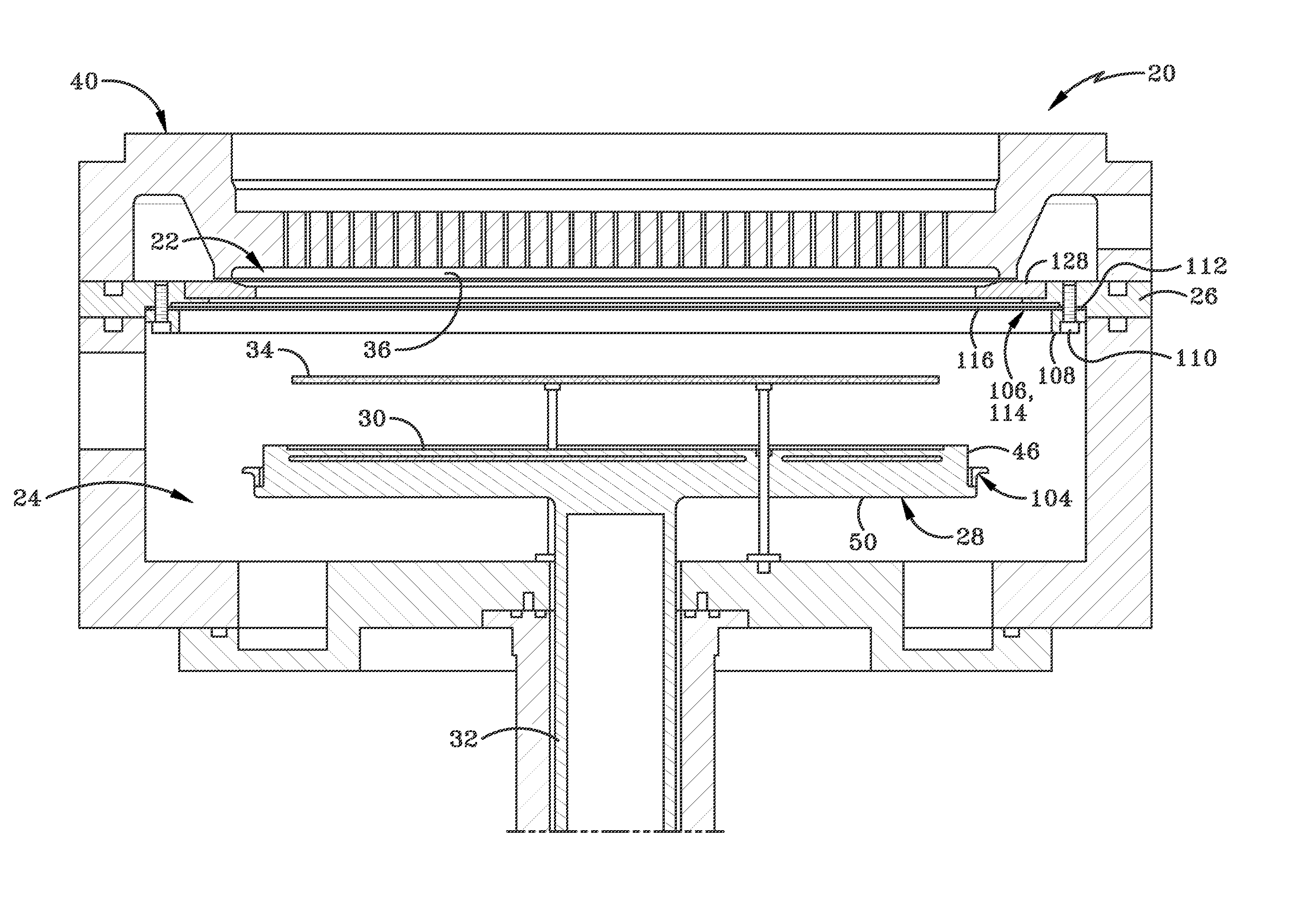
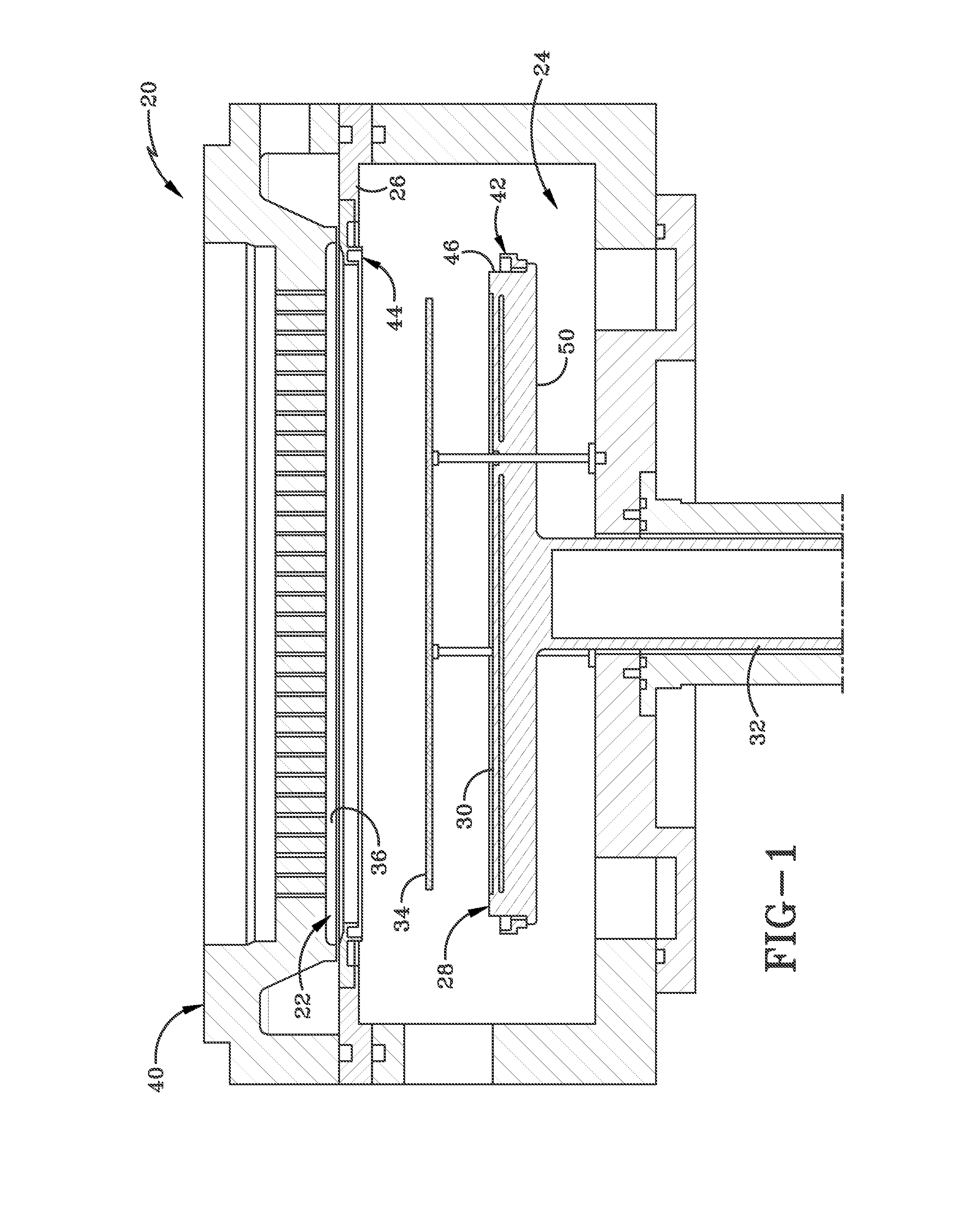
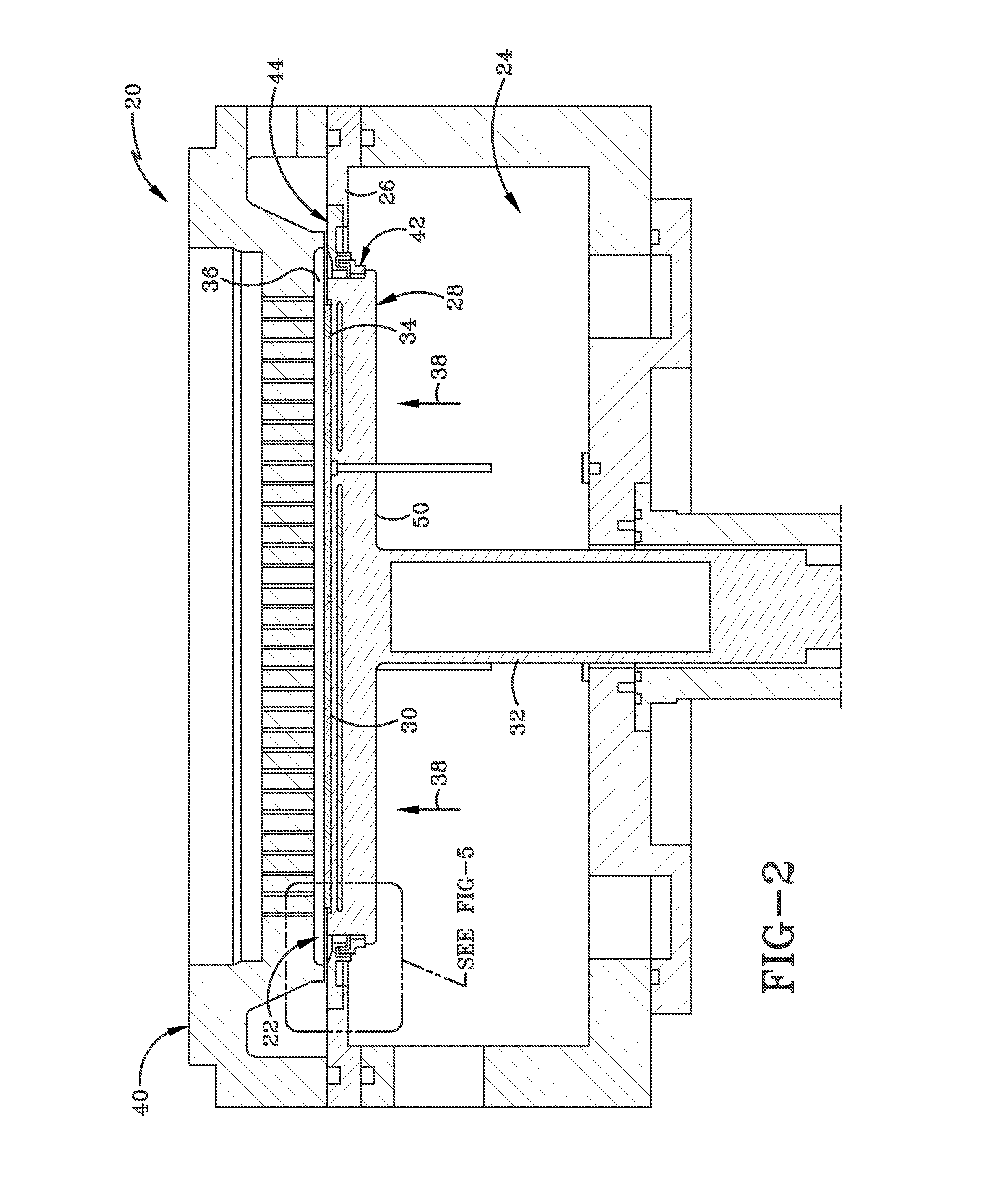
The patent describes a reaction chamber for processing substrates. The chamber has an upper region for processing the substrate, a lower region for loading the substrate, and a susceptor that can move within the chamber. The chamber has two sealing members that can be engaged with each other to limit communication between the upper and lower regions. The sealing members are positioned on the susceptor and can seal the gap between them. The chamber also has a showerhead and a second sealing member positioned between the showerhead and the first sealing member. The second sealing member is flexible and can be deflected by the susceptor when the chamber is in a processing position. The second sealing member can be secured within the lower region of the chamber. The first and second sealing members have protrusions that can be nested together when the susceptor is in a processing position. The sealing members are made of quartz and can have a tortuous path between them. The second sealing member can have notches and a plurality of radially aligned slits. The patent also describes an isolation device that includes the first and second sealing members.

Problems solved by technology

A regularly occurring issue in dual chamber reactors is deposition particles coating the lower chamber walls and requiring more frequent chamber cleaning.
It can also be difficult to heat a substrate being processed in a substrate processing tool.
Such within-substrate temperature variations may lead to within-substrate processing non-uniformities.
In some settings, substrates exhibiting such non-uniformities may produce defective devices.
Further, deposition product may be deposited in the lower processing chamber, leading to reduced temperatures in the reaction chamber and therefore increased power consumption to overcome the inadequate heating.
Additionally, the build-up of deposition product in the chamber can lead to premature chamber cleaning requirements and increased costs.

Method used


Image

  • Chamber sealing member
  • Chamber sealing member
  • Chamber sealing member

Examples


Embodiment Construction

[0029]The present aspects and implementations may be described in terms of functional block components and various processing steps. Such functional blocks may be realized by any number of hardware or software components configured to perform the specified functions and achieve the various results. For example, the present aspects may employ various sensors, detectors, flow control devices, heaters, and the like, which may carry out a variety of functions. In addition, the present aspects and implementations may be practiced in conjunction with any number of processing methods, and the apparatus and systems described may employ any number of processing methods, and the apparatus and systems described are merely examples of applications of the invention.

[0030]FIGS. 1 and 2 illustrate views of a reaction chamber 20 in a loading / unloading position and a processing position, respectively. Reaction chamber 20 may include an upper region 22 and a lower region 24, which may be separated by...


PUM

PropertyMeasurementUnit
Timeaaaaaaaaaa
Temperatureaaaaaaaaaa
Flexibilityaaaaaaaaaa

Abstract

A reaction chamber including an upper region for processing a substrate, a lower region for loading a substrate, a susceptor movable within the reaction chamber, a first sealing member positioned on a perimeter of the susceptor, a second sealing member positioned between the upper region and the lower region, wherein the first and second sealing members are selectively engaged with one another to limit communication between the upper region and the lower region.

Description

CROSS-REFERENCE TO RELATED APPLICATIONS[0001]This application claims the benefit of U.S. Provisional Application No. 61 / 563,232, filed on Nov. 23, 2011, the disclosure of which is hereby incorporated herein by reference.BACKGROUND[0002]Thin film deposition reaction chambers are generally manufactured with a single chamber or a dual chamber. In the dual chamber arrangement, the two chambers may be oriented with one chamber vertically above the second chamber. The upper chamber is used for the processing of the substrate, while the lower chamber is used for substrate loading and unloading. A regularly occurring issue in dual chamber reactors is deposition particles coating the lower chamber walls and requiring more frequent chamber cleaning.[0003]It can also be difficult to heat a substrate being processed in a substrate processing tool. Variation in substrate heating may lead to within-substrate temperature variations. Such within-substrate temperature variations may lead to within-s...

Claims


Application Information

Patent Timeline
IPC IPC(8): B01J8/00
CPCB01J8/0035C23C16/4585B01J19/0073H01L21/67126C23C16/4409
Inventor HALPIN, MICHAELSHERO, ERICWHITE, CARLALOKOZAI, FREDWINKLER, JERRYDUNN, TODD
Owner ASM IP HLDG BV
Learn More