Electrical signal connector

Active Publication Date: 2013-05-23
EZCONN
View PDF2 Cites 8 Cited by
  • Summary
  • Abstract
  • Description
  • Claims
  • Application Information

AI Technical Summary

Benefits of technology

[0012]As the barrel is sleeved onto the cylindrical casing and kept between the first tubular deformable portion of the cylindrical casing and the locknut, moving the barrel toward the first tubular deformable portion of the cylindrical casing does not bias the barrel relative to the cylindrical casing, assuring alignment accuracy and avoiding the use of any extra parts.
[0013]Further, when forcing the tapered inner surface portion of the barrel against the tapered abutment face of the cylindrical casing during installation, the outside annular flange and second tubular deformable port

Problems solved by technology

Due to critical requirements from consumers, signal transmission requires high stabil

Method used


Image

  • Electrical signal connector
  • Electrical signal connector
  • Electrical signal connector

Examples


Embodiment Construction

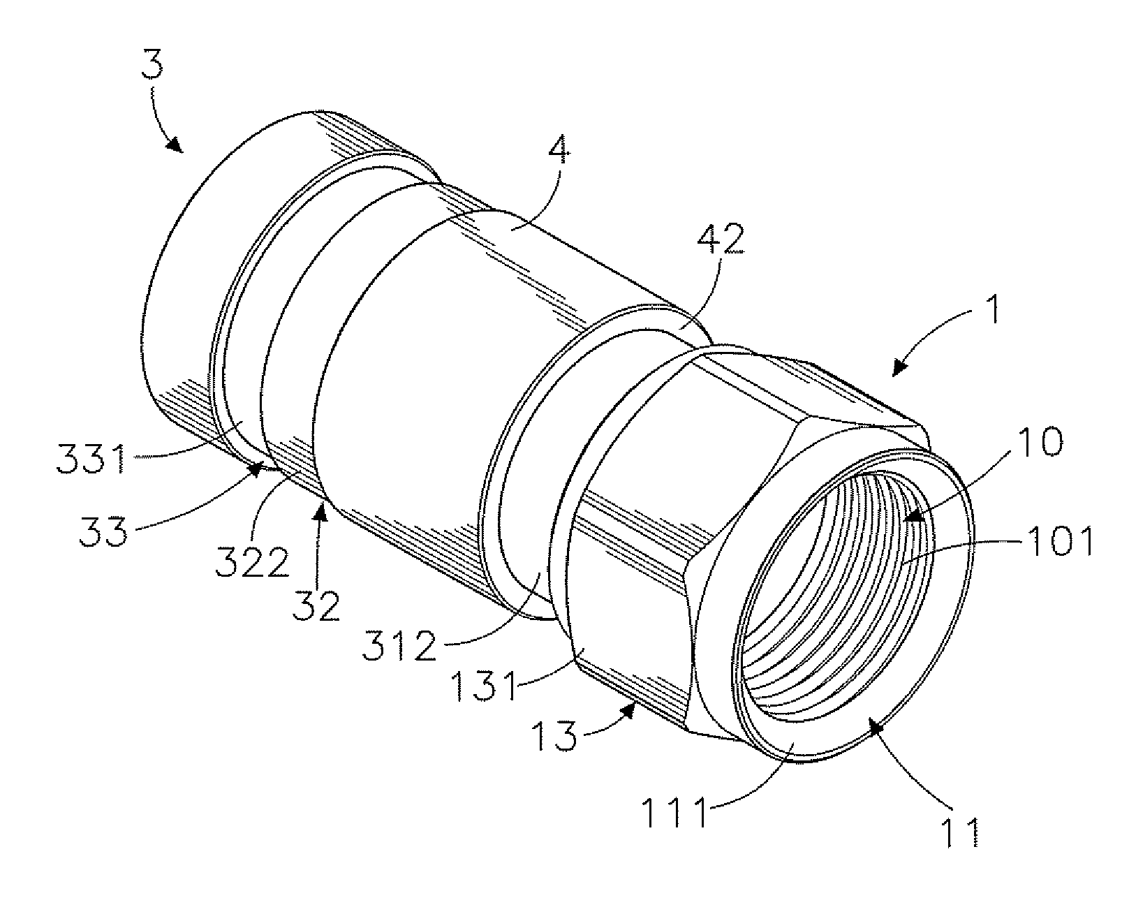
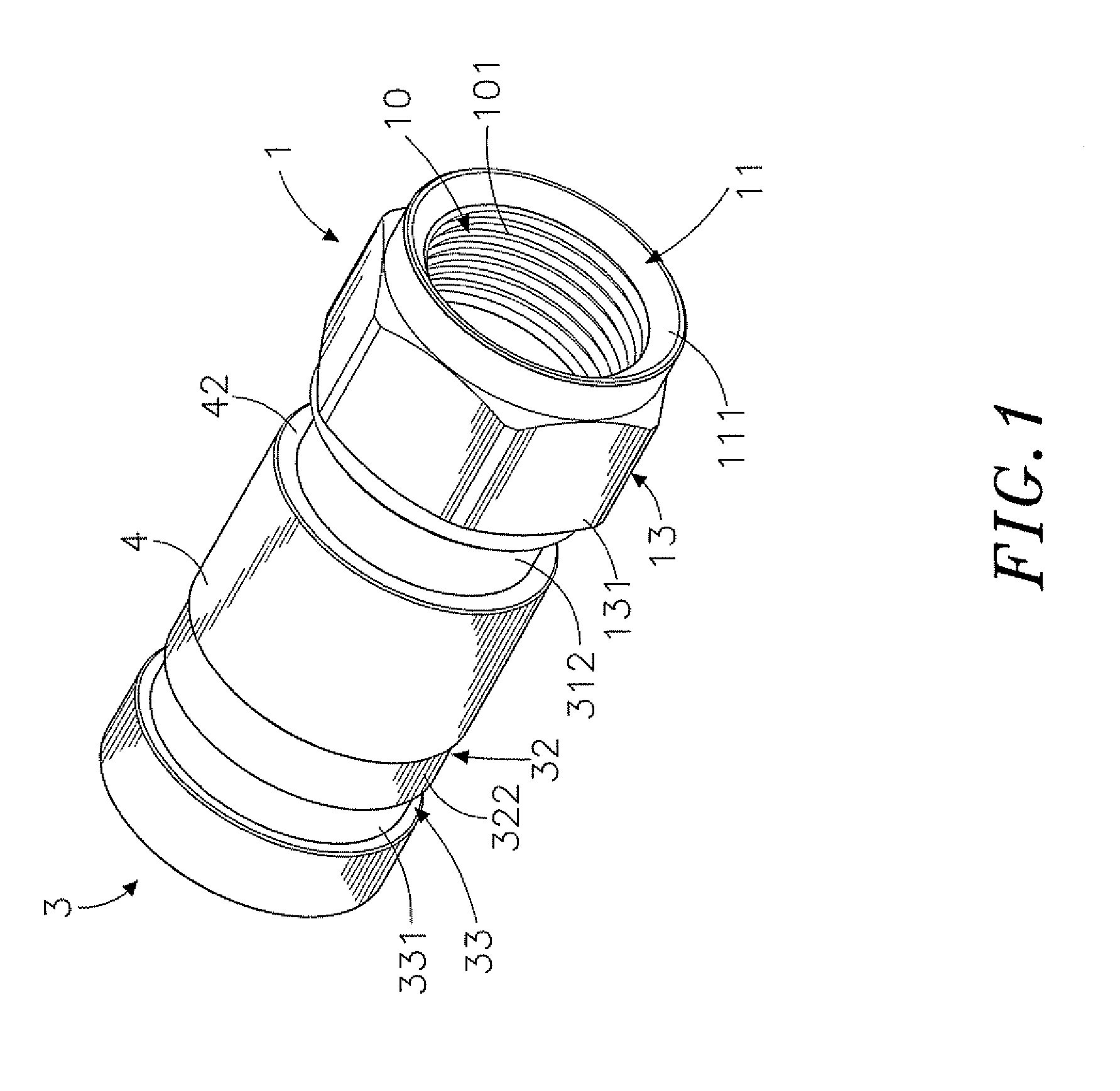
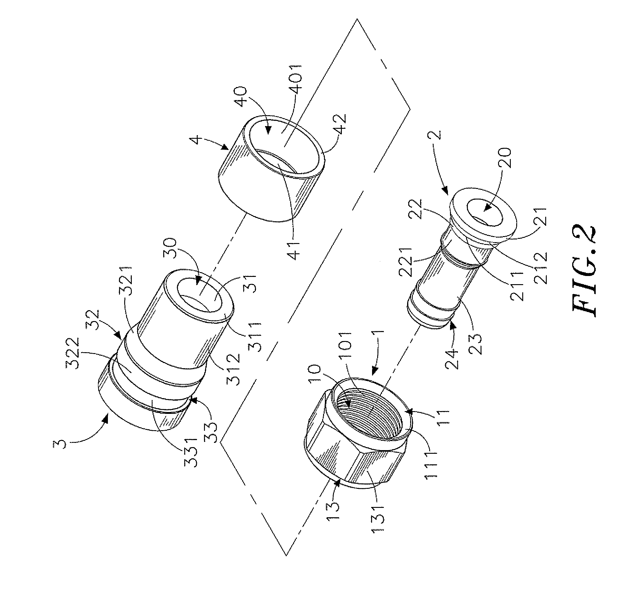
[0027]Referring to FIGS. 1˜4, an electrical signal connector in accordance with the present invention is shown comprising a locknut 1, a core tube 2, a cylindrical casing 3 and a barrel 4.

[0028]The locknut 1 is a metal member shaped like a polygonal screw nut, comprising a center hole 10 axially extending through opposing front and rear sides thereof, an inner thread 101 extending around the inside wall thereof within the center hole 10, an annular locating flange 11 located on the front side thereof and defining therein an orifice 111 in communication with one end of the center hole 10, a retaining portion 12 located on the rear side thereof around the center hole 10, and an operating portion 13 formed of a hexagonal wall 131 and disposed around the center hole 10 between the annular locating flange 11 and the retaining portion 12. The retaining portion 12 comprises a stepped shoulder 121 extending around the other end of the center hole 10 and a beveled abutment face 122 located o...


PUM


Abstract

An electrical connector includes a locknut having an annular locating flange, a core tube for receiving the copper core, inner dielectric insulator and aluminum foil shield of a coaxial cable and supporting the braided metal wrapper and outer plastic sheath of the coaxial cable, a casing surrounding the core tube and having first and second tubular deformable portions and a vertical rear stop edge, and a barrel mounted on the casing between the first tubular deformable portion and the locknut and having a tapered inner surface portion and movable to compress the first and second tubular deformable portions against the coaxial cable and the core tube and an annular front stop edge for stopping a crimping tool used to crimp the casing.

Description

[0001]This application claims the priority benefit of Taiwan patent application number 100215901 file on Aug. 25, 2011.BACKGROUND OF THE INVENTION[0002]1. Field of the Invention[0003]The present invention relates electrical connectors and more particularly to an electrical signal connector consisting of a metal locknut, a core tube, an elastic cylindrical casing and a barrel for quick connection with a coaxial cable by means of moving the barrel relative to the cylindrical casing to deform the cylindrical casing without causing damage to the coaxial cable.[0004]2. Description of the Related Art[0005]Following fast development of electronic and multimedia technology, advanced TV, audio system, video player, digital camera, video game machine and may other electronic products have been continuously created to serve people. Due to critical requirements from consumers, signal transmission requires high stability and rapid speed. To achieve high performance, high quality audio and video ...

Claims


Application Information

Patent Timeline
IPC IPC(8): H01R9/05
CPCH01R13/405H01R9/05
Inventor WEI, KAI-CHIHCHIEN, MING-FENGHOLLAND, MICHAEL
Owner EZCONN
Why Eureka
Try Eureka