
Fastener stock and device for use in dispensing plastic fasteners therefrom

a technology of plastic fasteners and fasteners, which is applied in the field of plastic fasteners, can solve the problems of variable needle spacing capabilities of fastener dispensing devices, affecting the quality of fastener stock,

Active Publication Date: 2013-05-30
AVERY DENNISON CORP
View PDF13 Cites 7 Cited by
  • Summary
  • Abstract
  • Description
  • Claims
  • Application Information

AI Technical Summary

Benefits of technology

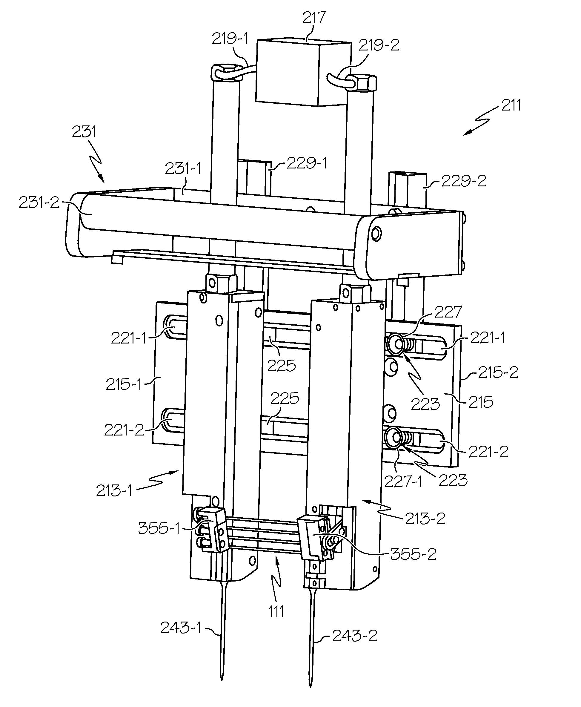
The present invention provides a fastener dispensing device that reduces stress on each fastener during ejection through the hollow needles. Additionally, the device allows for flexibility in adjusting the spacing between the needles, making it suitable for a wider range of applications. The device also reliably aligns the fastener stock with the needles before rail severing.

Problems solved by technology

In this capacity, the dispensed fastener serves to secure the article to the display card in an inconspicuous and unobtrusive manner.
Although well known in the art, fastener dispensing devices with variable needle spacing capabilities typically suffer from a few notable shortcomings.
As a result, the spacing range between needles is generally limited by the length of the axle on which the movable needle block is mounted and, more generally, by the overall width of the VNS module housing.
As can be appreciated, it has been found that this restriction on the maximum spacing between needles precludes use of traditional VNS devices in certain larger-scale packaging applications (e.g., in securing larger sized objects to display cards), which is highly undesirable.
As a second shortcoming, fastener dispensing devices of the type described above exert a significant amount of stress on each fastener during the ejection process which, in turn, can lead to inadvertent breakage of the fastener, which is highly undesirable.
However, because traditional fastener dispensing devices are designed to simultaneously eject both cross-bars of the same fastener through their corresponding needles (i.e., with the cross-bars ejected in phase with one another), the cumulative effect of the temporary stress applied to the fastener often results in fastener breakage during the ejection process.
As a consequence, a considerable amount of misalignment, or drift, of the lowermost cross-links within the device is experienced prior to the side rail cutting process.
Ladder stock drift in turn causes the device to cut each side rail at a location away from the exact midpoint between successive fasteners, thereby resulting in fasteners that fail to have the optimal H-shaped configuration.
In response thereto, a considerable degree of user adjustment is often required in order to maintain accurate and consistent cutting of side rails, which is both labor-intensive and often unreliable.
As a consequence, it to be understood that the process for removing, repairing and / or replacing needles is not only labor-intensive and time-consuming but also requires the use of an additional tool, such as a screwdriver, which is highly undesirable.

Method used


Image

  • Fastener stock and device for use in dispensing plastic fasteners therefrom
  • Fastener stock and device for use in dispensing plastic fasteners therefrom
  • Fastener stock and device for use in dispensing plastic fasteners therefrom

Examples


Embodiment Construction

[0052]The apparatuses and methods disclosed in this document are described in detail by way of examples and with reference to the figures. Unless otherwise specified, like numbers in the figures indicate references to the same, similar, or corresponding elements throughout the figures. It will be appreciated that modifications to disclosed and described examples, arrangements, configurations, components, elements, apparatuses, methods, materials, etc. can be made and may be desired for a specific application. In this disclosure, any identification of specific shapes, materials, techniques, arrangements, etc. are either related to a specific example presented or are merely a general description of such a shape, material, technique, arrangement, etc. Identifications of specific details or examples are not intended to be, and should not be, construed as mandatory or limiting unless specifically designated as such. Selected examples of apparatuses and methods are hereinafter disclosed a...


PUM


Abstract

A device for dispensing a plastic fastener from a supply of ladder-type fastener stock includes a pair of separate modules that are independently pneumatically powered by a common air source. Each module is adapted to receive and index a corresponding side rail of the fastener stock, separate a cross-bar therefrom and eject the separated cross-bar out through a sharpened needle. As a feature of the invention, the pair of modules ejects the cross-bars of the dispensed fastener in an offset relationship to minimize fastener stress. As another feature of the invention, the pair of modules is independently slidably coupled to a common mounting plate. In this manner, the spacing and angular orientation between the modules are adjustable. As another feature of the invention, the feed mechanism includes a feed pawl that selectively engages outwardly facing notches formed in the side rail to ensure accurate alignment prior to the severing process.

Description

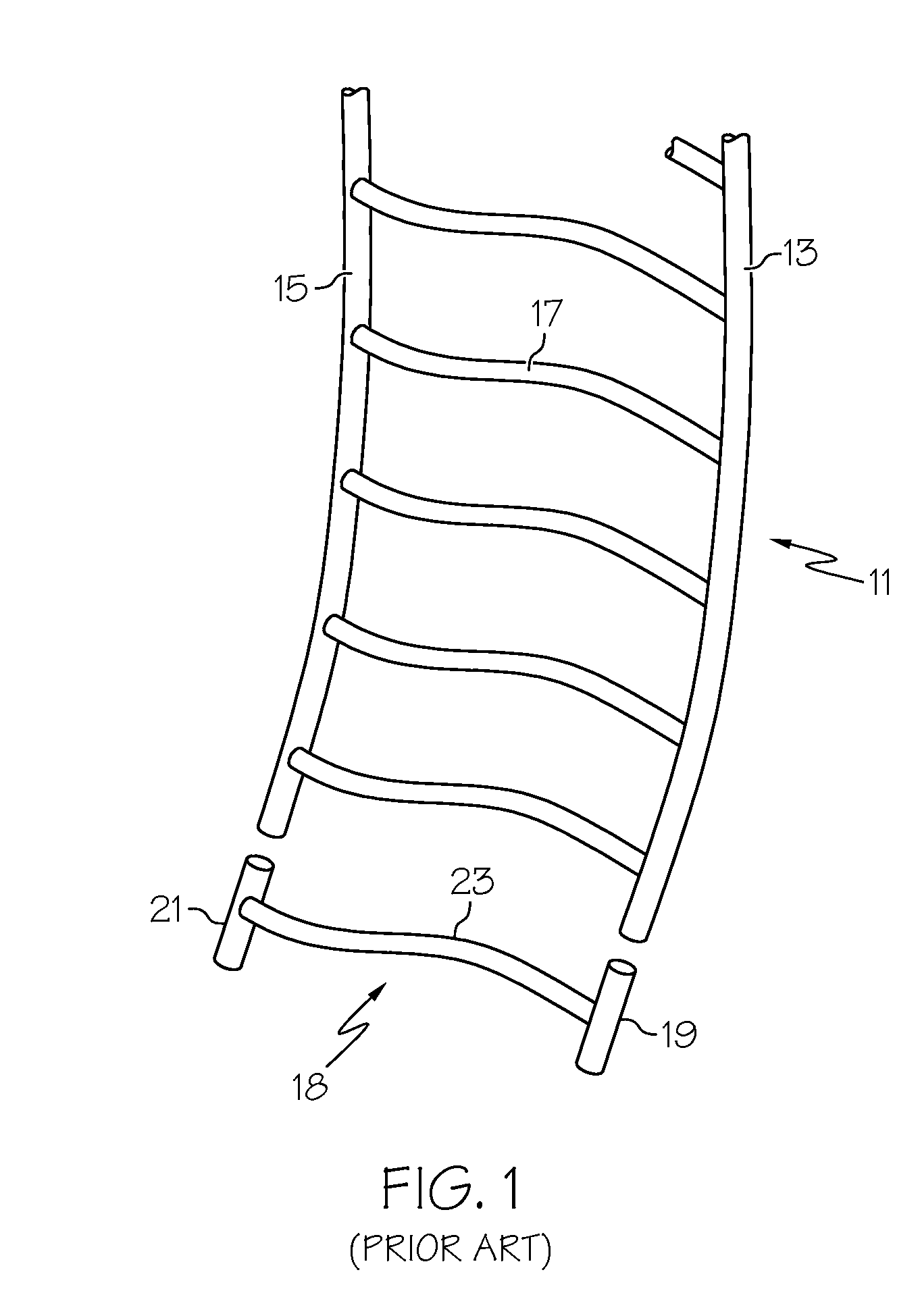
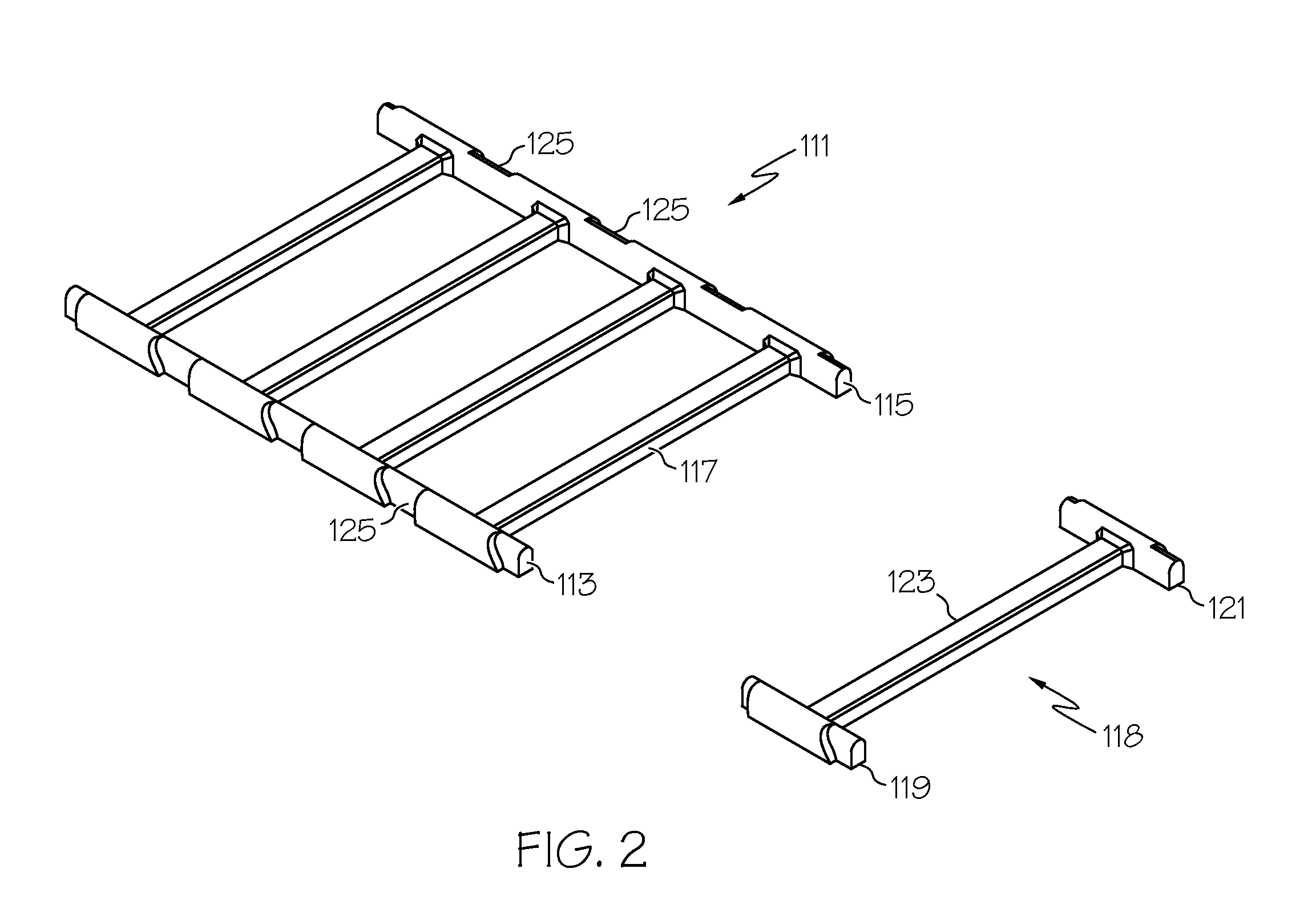
FIELD OF THE INVENTION[0001]The present invention relates generally to plastic fasteners and more particularly to devices used in the dispensing of plastic fasteners.BACKGROUND OF THE INVENTION[0002]Plastic fasteners (also commonly referred to in the art as plastic attachments) are well known in the art and commonly used to couple articles of commerce to packaging, buttons to fabric, merchandising tags to articles of commerce, or, in general, any two desired articles. One type of plastic fastener which is widely used in commerce is manufactured in an H-shaped configuration, with two shortened parallel cross-bars, or T-bars, interconnected at their approximate midpoints by a thin, flexible filament that extends orthogonally therebetween.[0003]Plastic fasteners of the type described above are commonly fabricated as part of continuously connected fastener stock that is produced from one or more flexible plastic materials, such as nylon and polypropylene, using conventional molding or s...

Claims


Application Information

Patent Timeline
Patent Type & Authority Applications(United States)
IPC IPC(8): B65C7/00G09F3/14B65D83/00
CPCG09F3/14Y10T24/4691B65C7/008B65C7/003A41H37/008
Inventor COOPER, WILLIAM J.
Owner AVERY DENNISON CORP
Learn More