
Radiography device

a radiographic image and apparatus technology, applied in the field of can solve the problems of columnar crystals being inadvertently subjected to stress, radiographic image capturing apparatus being subjected to external shock,

Inactive Publication Date: 2013-05-30
FUJIFILM CORP
View PDF0 Cites 29 Cited by
  • Summary
  • Abstract
  • Description
  • Claims
  • Application Information

AI Technical Summary

Benefits of technology

The patent aims to prevent the cracking of columnar crystals in a radiographic image capturing apparatus caused by external shocks or inadvertent stresses. It proposes a solution to keep the scintillator and radiation conversion panel separate from each other before the external shock is applied, and to quickly restore them to the original state after the shock. This prevents damage to the columnar crystals and ensures good performance of the radiographic image capturing apparatus. In addition, the scintillator has a convex surface facing the radiation conversion panel, which prevents cracking of the columnar crystals during frequent contact and separation.

Problems solved by technology

For example, a doctor or a radiological technician may drop the radiographic image capturing apparatus by mistake during transport.
In such a case, the radiographic image capturing apparatus is subjected to an external shock, and the columnar crystals are inadvertently subjected to a stress.
Consequently, the columnar crystals may be broken (fractured) or cracked, resulting in deterioration in the performance of the radiographic image capturing apparatus such as radiographic image blurring, etc.

Method used


Image

  • Radiography device
  • Radiography device
  • Radiography device

Examples


Embodiment Construction

[0044]A preferred embodiment of the radiographic image capturing apparatus of the present invention will be described in detail below with reference to FIGS. 1 to 16B.

[Constitution of the Embodiment]

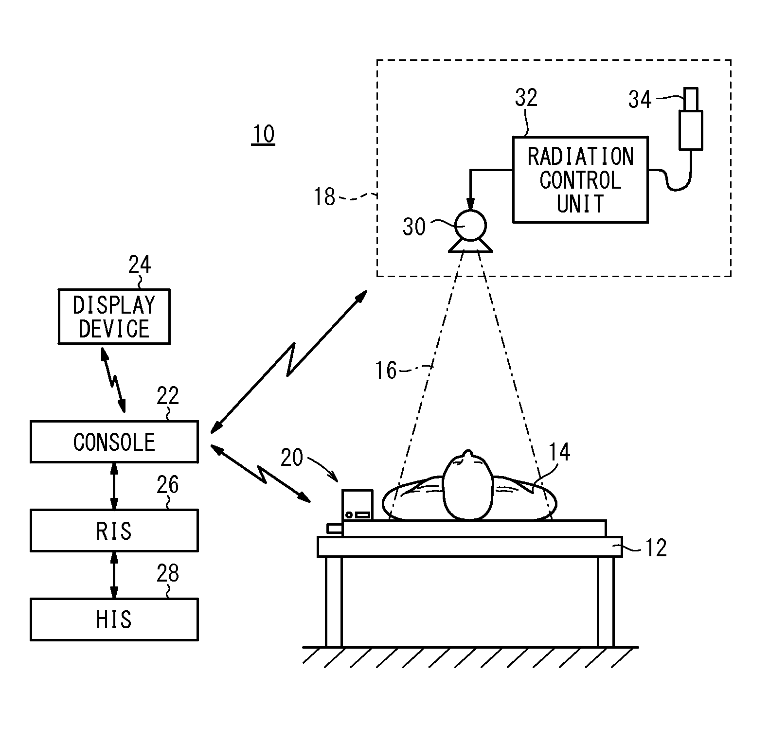
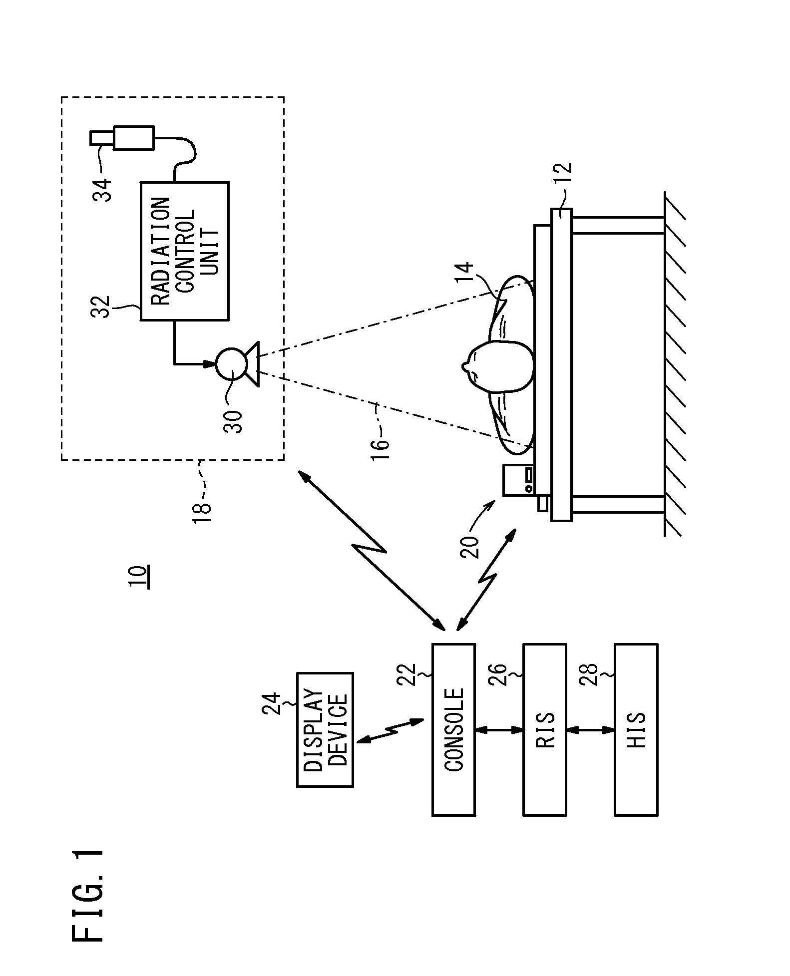
[0045]FIG. 1 is a schematic view of a radiographic image capturing system 10 having an electronic cassette 20 (radiographic image capturing apparatus) according to this embodiment.

[0046]The radiographic image capturing system 10 has a radiation output apparatus 18 for applying a radiation 16 to a subject 14 such as a patient lying on an image capturing base 12 such as a bed, the electronic cassette 20 for detecting the radiation 16 that has passed through the subject 14 and converting the detected radiation 16 into a radiographic image, a console 22 for controlling the entire radiographic image capturing system 10 and receiving operation input by a doctor or a radiological technician (hereinafter referred to simply as the doctor), and a display device 24 for displaying the captured radio...


PUM


Abstract

In this radiography device, the radiation conversion panel side of a scintillator is formed in a convex shape towards the radiation conversion panel, the end portions of columnar crystals are formed at said side, and the end portions of the columnar crystals can contact the radiation conversion panel.

Description

CROSS-REFERENCE TO RELATED APPLICATIONS AND PRIORITY CLAIM[0001]This application is a Continuation of International Application No. PCT / JP2011 / 064398 filed on Jun. 23, 2011, which was published under PCT Article 21(2) in Japanese, which is based upon and claims the benefit of priority from Japanese Patent Application No. 2010-194941 filed on Aug. 31, 2010, the contents all of which are incorporated herein by reference.TECHNICAL FIELD[0002]The present invention relates to a radiographic image capturing apparatus (radiography device) having a scintillator for converting a radiation into a visible light and a radiation conversion panel for converting the visible light into an electric signal.BACKGROUND ART[0003]In the medical field, radiographic image capturing apparatuses have been widely used for detecting a radiation applied to a subject from a radiation source and passed through the subject to acquire a radiographic image of the subject. For example, the radiographic image capturin...

Claims


Application Information

Patent Timeline
Patent Type & Authority Applications(United States)
IPC IPC(8): G01T1/202
CPCA61B6/4283G01T1/202A61B6/4233A61B6/563
Inventor NAKATSUGAWA, HARUYASUNISHINO, NAOYUKIOHTA, YASUNORIIWAKIRI, NAOTO
Owner FUJIFILM CORP
Learn More