Damper

a technology of damper and needle valve, which is applied in the direction of shock absorbers, steering devices, cycle equipment, etc., can solve the problems of sacrificing economic efficiency and vehicle mountability, affecting the performance of the vehicle, and the variable range of the flow path of the needle valve becoming inevitably smaller, so as to accurately adjust the damping force generated

Active Publication Date: 2013-05-30
KYB CORP
View PDF3 Cites 15 Cited by
  • Summary
  • Abstract
  • Description
  • Claims
  • Application Information

AI Technical Summary

Benefits of technology

[0008]The above damper can accurately adjust a damping force generated in the damper since a stable fl

Problems solved by technology

To cause the stepping motor to output a high torque, the stepping motor is enlarged and cost thereof increases, thereby sacrificing economic efficiency and vehicle mountability.
However, since the above damper cannot completely block the passage, a flow path variabl

Method used


Image

  • Damper
  • Damper
  • Damper

Examples


Embodiment Construction

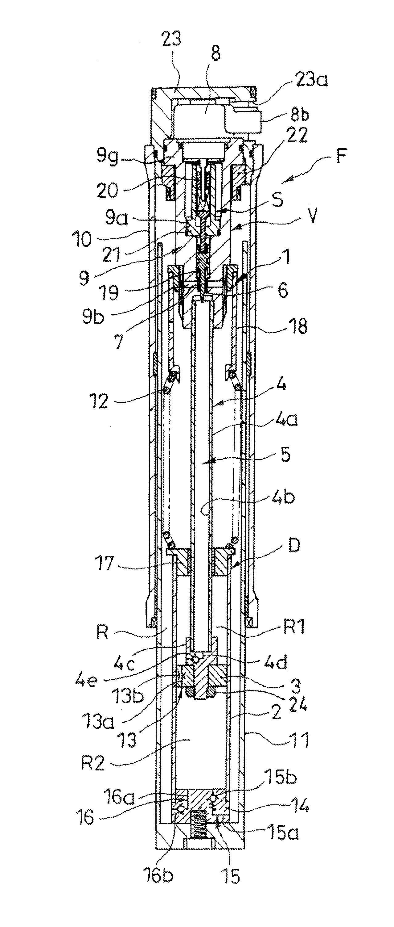
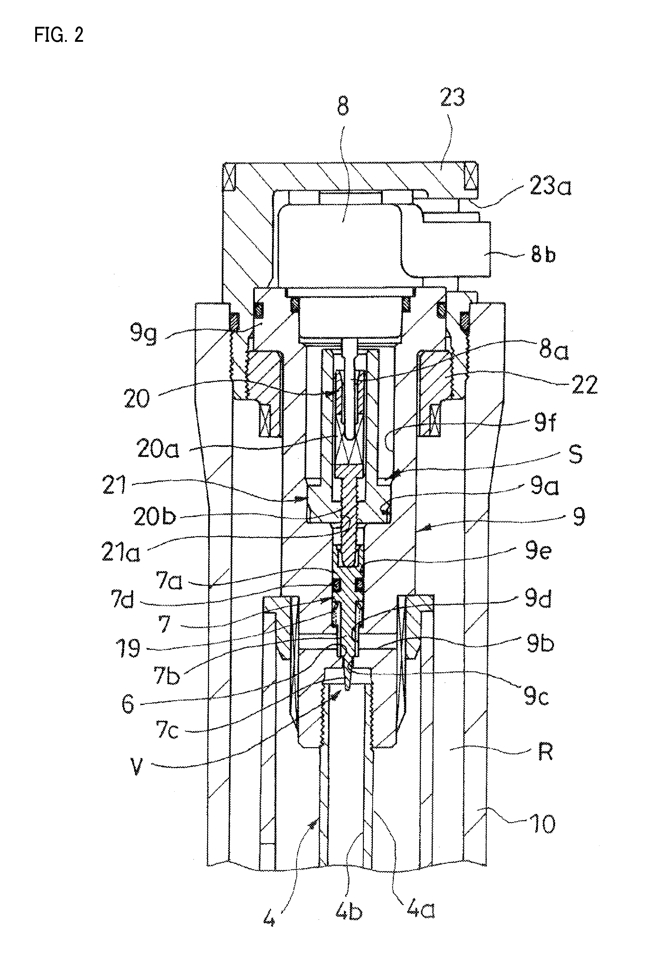
[0019]As shown in FIG. 1, a damper 1 in this embodiment includes a damper main body D with a cylinder 2, a piston 3 and a piston rod 4 and a damping force adjustment mechanism V with a flow path 5, a valve seat 6, a valve body 7 and a motor 8.

[0020]The piston 3 is slidably inserted into the cylinder 2 to partition the interior of the cylinder 2 into an extension side chamber R1 and a compression side chamber R2. The piston rod 4 is inserted into the cylinder 2 to be coupled to the piston 3. The flow path 5 permits the passage of a fluid only when the damper main body D extends. The valve seat 6 is provided at an intermediate position of the flow path 5. The valve body 7 is movable back and forth relative to the valve seat 6. The motor 8 adjusts a flow path area by driving and moving the valve body 7 back and forth relative to the valve seat 6.

[0021]Each component is described in detail below. The damper main body D is housed in a front fork F formed by a vehicle body side tube 10 an...


PUM


Abstract

Damper is provided with damper main body including cylinder, piston being slidably inserted into cylinder to partition interior of cylinder into extension and compression chambers, and piston rod being inserted into cylinder to be coupled to piston, and damping force adjustment mechanism including flow path permitting passage of fluid only during either extension or contraction, valve seat being provided at intermediate position of flow path, valve body being movable back and forth relative to valve seat, and motor driving and moving valve body back and forth relative to valve seat to adjust flow path area of flow path. Damper energizes motor to move valve body distance, which is two-fold or more of distance from separated position where valve body is separated from valve seat to seated position where valve body is seated on valve seat, when flow path is blocked by moving valve body from separated position to seated position.

Description

TECHNICAL FIELD[0001]The present invention relates to a damper.BACKGROUND ART[0002]A damper is built in a front fork of a two-wheel vehicle and adjusts a damping force by a motor. JP2008-14431 discloses a damper including a damper main body with a cylinder, a piston and a piston rod, a passage, a needle valve and a stepping motor.[0003]The cylinder is coupled to an outer tube. The piston is slidably inserted into the cylinder to partition the interior of the cylinder into a compression side chamber and an extension side chamber. The piston rod is inserted into the cylinder, one end is coupled to an inner tube slidably inserted into the outer tube and the other end is coupled to the piston.[0004]The passage allows communication between the compression side chamber and the extension side chamber of the damper main body. A check valve is provided at an intermediate position of the passage and permits only a flow from the compression side chamber toward the extension side chamber or, co...

Claims


Application Information

Patent Timeline
IPC IPC(8): B62K25/08F16F9/34
CPCB62K25/08B62K2025/048F16F2230/18F16F9/34F16F9/464F16F9/466
Inventor MOCHIZUKI, TAKAHISAAMANO, YUUKI
Owner KYB CORP
Why Eureka
Try Eureka