Vehicle brake device and method of controlling vehicle brake device

Active Publication Date: 2013-05-30
BOSCH CORP
View PDF7 Cites 12 Cited by
  • Summary
  • Abstract
  • Description
  • Claims
  • Application Information

AI Technical Summary

Benefits of technology

[0021]According to the invention, the brake device includes a booster, and the generation of the regenerative brake force is stopped in association with jump-in characteristics of the booster. According to this structure, the stop of the generation of the regenerative brake force is associated with the jump-in characteristics of the booster. Accordingly, it is possible to prevent reaction, which is applied from the master cylinder, from being affected by the change of the regenerative brake force by making the regenerative brake force substantially become zero when, for example, a jump-in area is ended. As a result, it is possible to maintain a good pedal feeling.
[0022]According to the invention, the driver-requested brake force is covered by only the hydraulic brake force at a time when a jump-in area is ended. According to this structure, since the driver-requested brake force is covered by only the hydraulic brake force at the time when the jump-in area is ended, a value of the regenerative brake force substantially becomes zero. Accordingly, it is possible to prevent reaction, which is applied from the master cylinder, from being affected by the change of the regenerative brake force, so that it is possible to maintain a good pedal feeling.
[0023]According to the invention, a

Problems solved by technology

Further, since the hydraulic brake control means does not open the pressure reducing valve when hydraulic pressure is prese

Method used


Image

  • Vehicle brake device and method of controlling vehicle brake device
  • Vehicle brake device and method of controlling vehicle brake device
  • Vehicle brake device and method of controlling vehicle brake device

Examples


Embodiment Construction

[0032]Embodiments of the invention will be described below with reference to FIGS. 1 to 6.

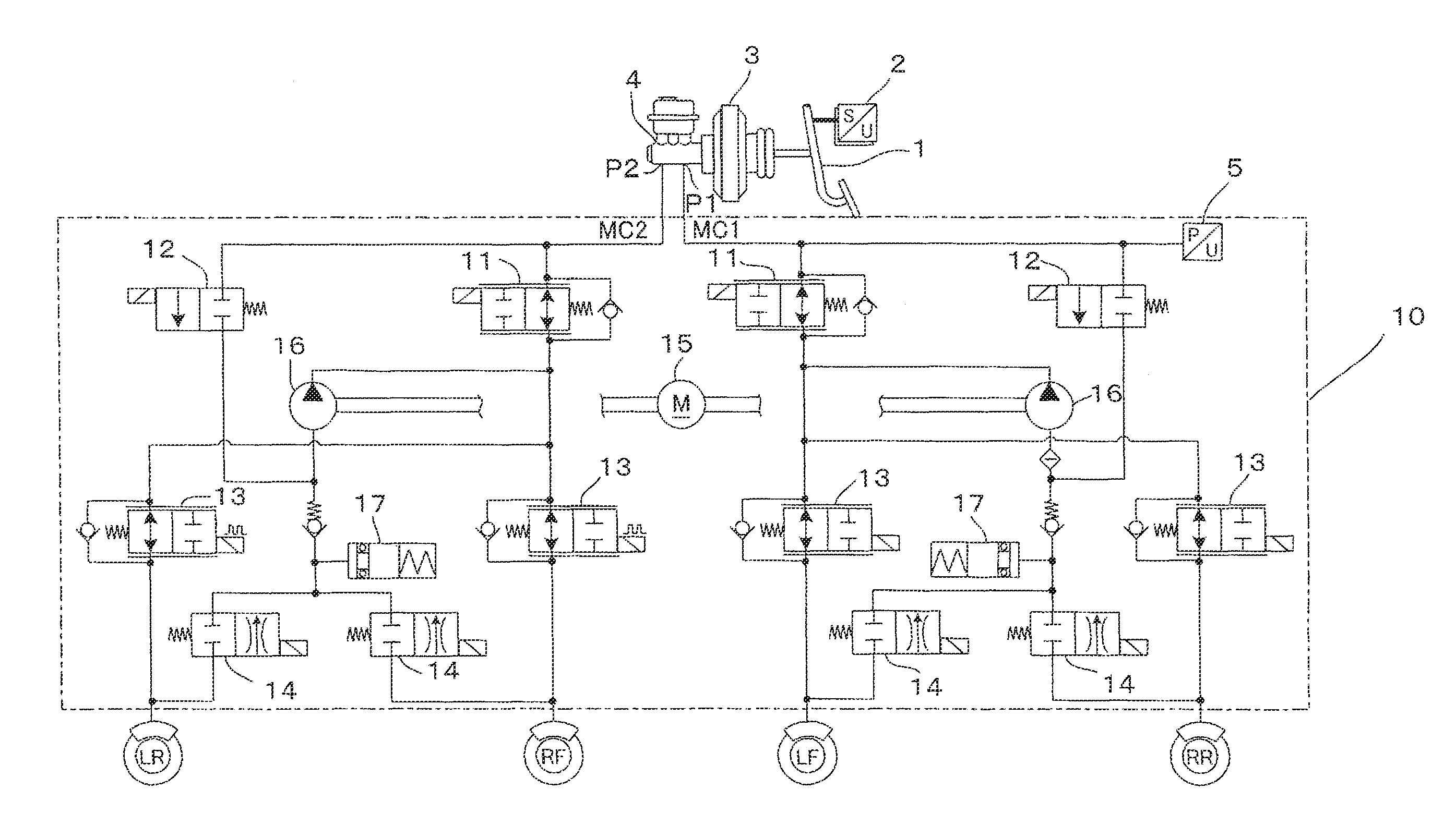
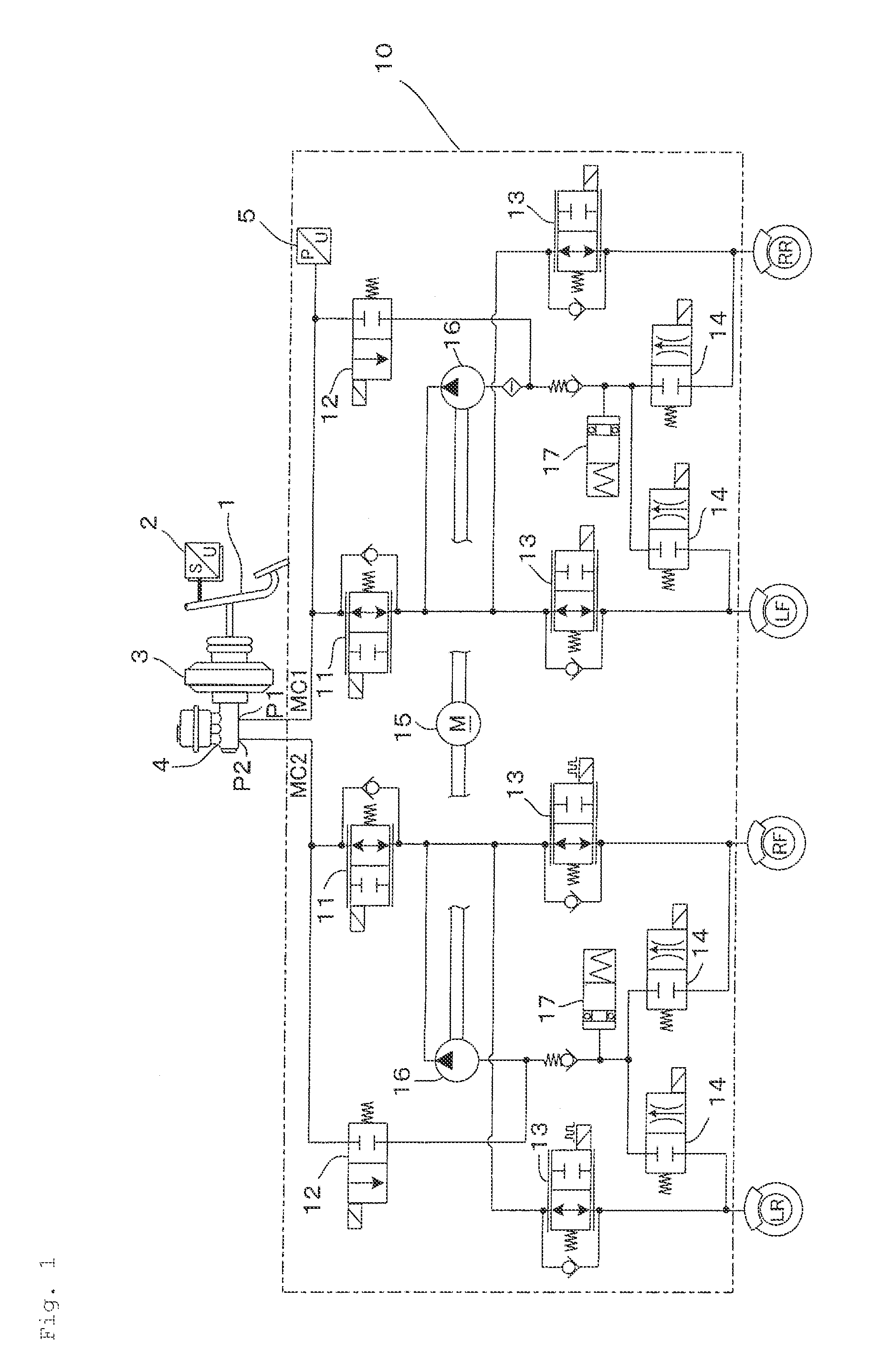
[0033]FIG. 1 shows an example of a hydraulic circuit 10, which forms hydraulic brake means, of a vehicle brake device to which the invention is applied. As shown in FIG. 1, this embodiment is applied to a so-called X-pipe type hydraulic circuit that includes two brake lines and brakes one front wheel and a rear wheel provided at the position diagonal to the front wheel as a pair on each line. However, the hydraulic circuit to which the invention is applied is not limited to the X-pipe type hydraulic circuit, and may be, for example, a so-called II-pipe type hydraulic circuit, which separately brakes front wheels and rear wheels, and the like. Further, the invention can be widely applied to vehicles that include not only four-wheeled vehicles but also two-wheeled vehicles.

[0034]The invention is applied to a vehicle brake device that includes regenerative brake means and hydraulic brake means and...


PUM


Abstract

There is provided a vehicle brake device that includes hydraulic brake means for generating a hydraulic brake force and regenerative brake means for generating a regenerative brake force and distributes the hydraulic brake force and the regenerative brake force for a driver-requested brake force. The hydraulic brake means includes a pressure reducing valve that reduces hydraulic pressure of wheel cylinders. The vehicle brake device includes hydraulic brake control means for maintaining the pressure reducing valve open while the driver-requested brake force is covered by only the regenerative brake force. The hydraulic brake control means does not open the pressure reducing valve when hydraulic pressure is present in the wheel cylinders.

Description

CROSS REFERENCE TO RELATED APPLICATIONS[0001]This application is a national phase application of PCT Application No. PCT / JP2011 / 068434, filed Aug. 12, 2011 which claims priority to Japanese Patent Application No. 201986 / 2010, filed Sep. 9, 2010, the entire contents of which are hereby incorporated by reference therein.BACKGROUND OF THE INVENTION[0002]The present invention relates to a vehicle brake device and a method of controlling the vehicle brake device, and more particularly, to a regenerative cooperative brake device that includes hydraulic brake means and regenerative brake means and a method of controlling the regenerative cooperative brake device.[0003]In the past, a so-called regenerative cooperative brake device, which applies a braking force to a vehicle by a hydraulic brake force generated according to the driver's operation of a brake pedal and a regenerative brake force generated by a regenerative brake device, has been known as a vehicle brake device. An object of a ...

Claims


Application Information

Patent Timeline
IPC IPC(8): B60T13/58B60T13/14
CPCB60T1/10Y02T10/7275B60T8/4872B60T13/586B60T13/662B60T13/686B60T2220/04B60T2270/604B60W10/08B60W10/188B60W30/18127B60L1/003B60L7/04B60L7/26B60L11/1805B60L15/2009B60L2240/461B60L2270/145B60T13/14Y02T10/7005B60W2510/182B60Y2300/89B60T7/042B60L50/52Y02T10/64Y02T10/70Y02T10/72
Inventor HAKIAI, MOTOMUTAKASAKI, YOSHIYASU
Owner BOSCH CORP
Why Eureka
Try Eureka