Transmission apparatus, reception apparatus, wireless communication system, control program and integrated circuit
a technology of transmission apparatus and reception apparatus, applied in the field of mobile communication technology, can solve the problems of limiting the number of reception antennas which can be arranged in the mobile station apparatus, limiting the improvement of spectrum efficiency, etc., and achieve the effects of reducing the amount of signal processing required for a nonlinear downlink mu-mimo, reducing the number of concurrent access users, and reducing the amount of mu-mimo
- Summary
- Abstract
- Description
- Claims
- Application Information
AI Technical Summary
Benefits of technology
Problems solved by technology
Method used
Image
Examples
first embodiment
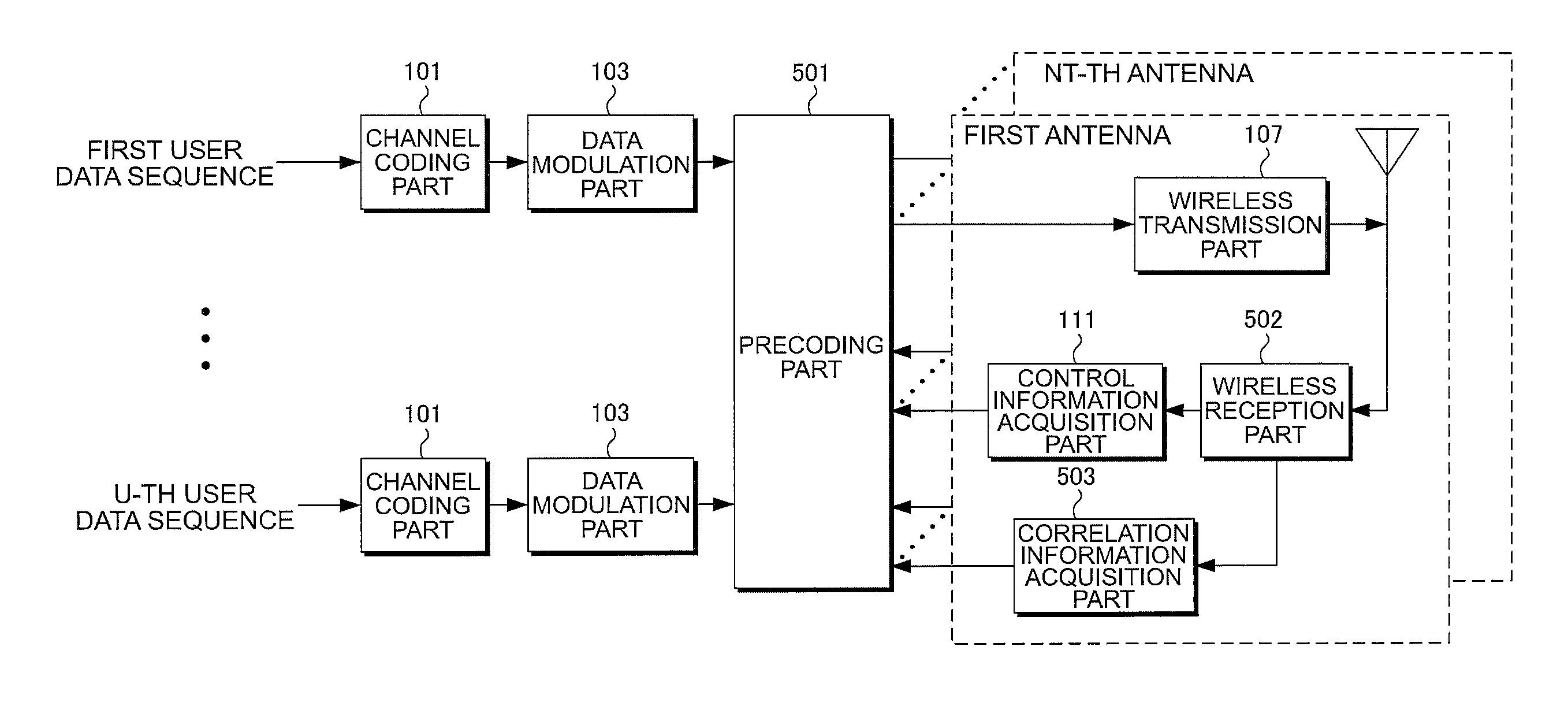
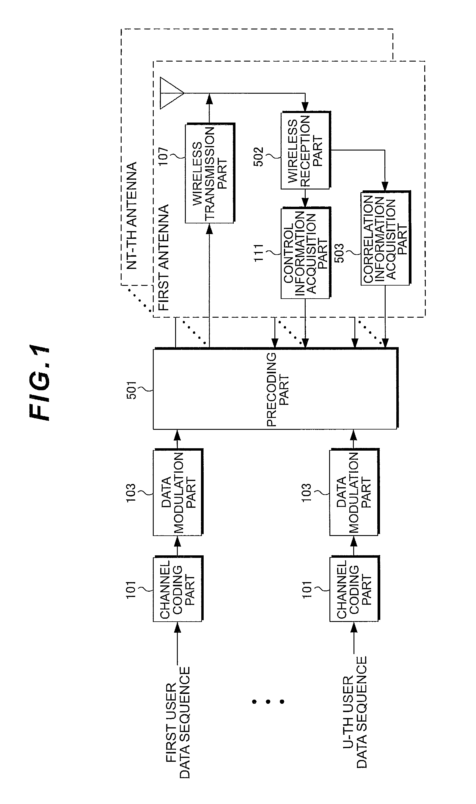
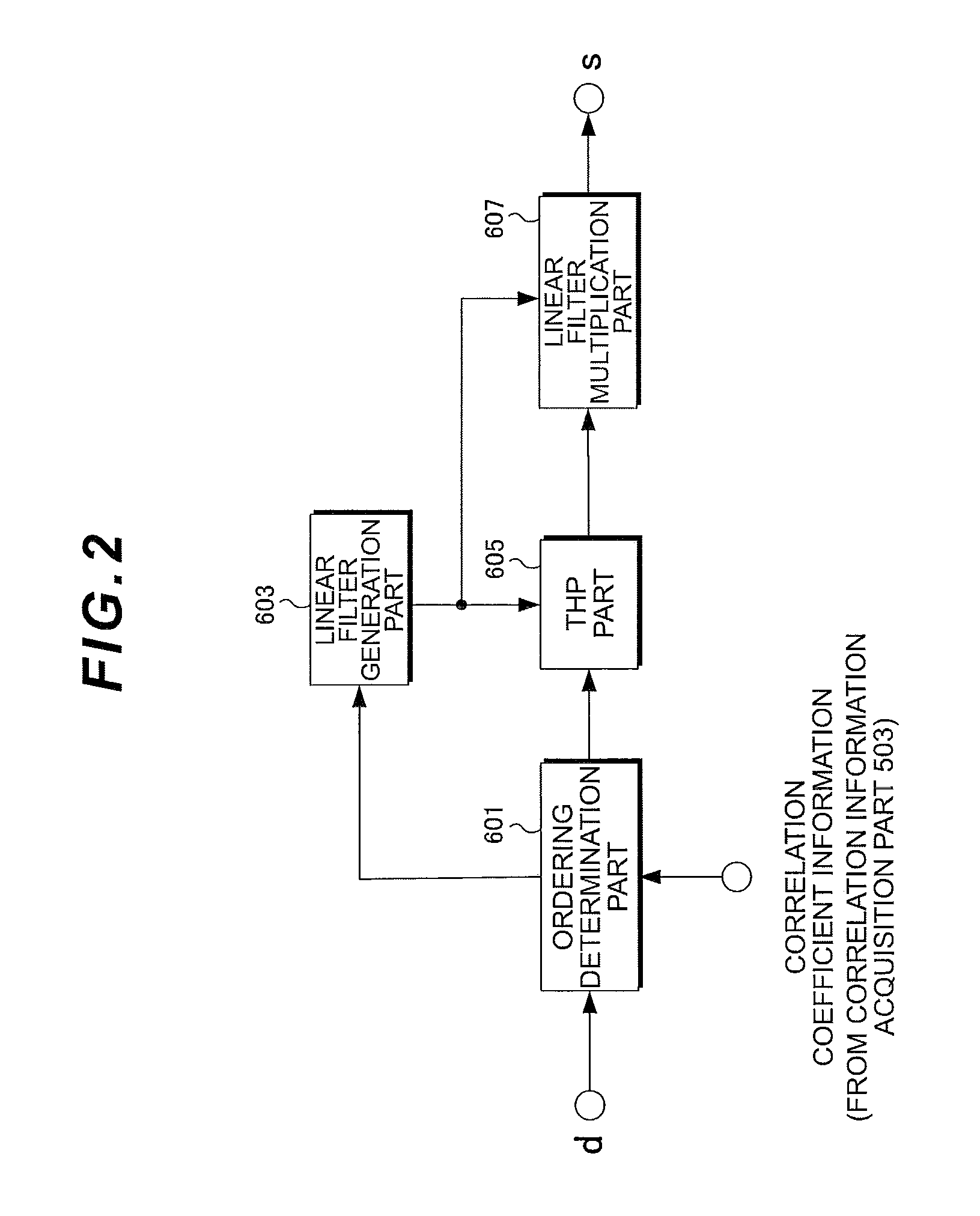
[0080]A first embodiment according to the present invention targets a downlink MU-MIMO transmission where U mobile station apparatuses (users) each having a single reception antenna (Nr=1) and a base station apparatus having Nt transmission antennas perform communication. It is to be noted that, in the first embodiment, although description is given with the number of reception antennas as Nr=1, the present invention is applicable also in the downlink MU-MIMO transmission between a plurality of mobile station apparatuses each having one or more reception antennas and the base station apparatus. Besides, in the present invention, the base station apparatus needs to know channel state information between each of mobile station apparatuses and the base station. Hereinafter, assuming that the channel state information is ideally notified to the base station apparatus from each of mobile station apparatuses, and that the base station apparatus knows the channel matrix H ideally, descript...
second embodiment
[0102]The first embodiment targets the case where all the users perform nonlinear interference suppression based on THP. On the other hand, in order to perform the nonlinear interference suppression based on THP, it is necessary to calculate an interference component to be subtracted (for example, the second term of Formula (6)) for all the users. Therefore, the interference component to be calculated will also increase as the number of users increases, which will cause increase in the calculation amount. The second embodiment targets a case of making intermingled users who do not perform the nonlinear interference suppression based on THP and users who perform it in order to reduce the calculation amount required for the calculation of this interference component. Note that, in the same way as the first embodiment, although description is given with the number of reception antennas of each of mobile station apparatuses as Nr=1, the second embodiment is applicable also in the downli...
third embodiment
[0113]In the first embodiment, performing the ordering in the Precoding part 501 of the base station apparatus based on only the transmission correlation coefficient enables the downlink MU-MIMO transmission with the calculation amount smaller than that of the conventional MU-MIMO BLAST ZF-THP system, but a little deterioration of transmission performances has arisen in contrast to the conventional system. A third embodiment targets a case where deterioration of transmission performances is suppressed to the minimum by not performing the ordering in the Precoding part 501 of the base station apparatus based on only the transmission correlation coefficient, but using together also the method of the conventional MU-MIMO BLAST ZF-THP system.
[0114]A base station apparatus configuration in the third embodiment is almost the same as that of the first and the second embodiments. What is different is a signal processing in the ordering determination part 601 in the Precoding part 501 of the...
PUM
 Abstract
Description
Claims
Application Information
 - R&D
- Intellectual Property
- Life Sciences
- Materials
- Tech Scout
- Unparalleled Data Quality
- Higher Quality Content
- 60% Fewer Hallucinations
Browse by: Latest US Patents, China's latest patents, Technical Efficacy Thesaurus, Application Domain, Technology Topic, Popular Technical Reports.
© 2025 PatSnap. All rights reserved.Legal|Privacy policy|Modern Slavery Act Transparency Statement|Sitemap|About US| Contact US: help@patsnap.com


