Method and apparatus for recovering depth information of image

a depth information and image technology, applied in image analysis, image enhancement, instruments, etc., to achieve the effect of enhancing spatio-temporal consistency and enhancing binocular disparity values of static pixels

Active Publication Date: 2013-05-30
SAMSUNG ELECTRONICS CO LTD
View PDF4 Cites 42 Cited by
  • Summary
  • Abstract
  • Description
  • Claims
  • Application Information

AI Technical Summary

Benefits of technology

[0011]The estimating of the binocular disparity map may include calculating the binocular disparity map of the middle view by repeatedly minimizing a value of an energy function through use of a back propagation (BP) algorithm, the value of the energy function being determined based on occlusion information associated with the middle view and the binocular disparity map of the middle view when the left image, the middle image, and the right image are provided, and enhancing the binocular disparity map of the middle view by fusing results obtained by applying different plane fittings to the binocular disparity map of the middle view.
[0013]The method may further include enhancing the binocular disparity map of the middle view using information associated with an optical flow among the frames.
[0017]The detecting may include enhancing a spatio-temporal consistency among the segmented dynamic regions through use of information associated with an optical flow among the frames.
[0018]The method may further include applying, to the middle views of the frames, bundle optimization and local three-dimensional (3D) line model-based temporal optimization so as to enhance binocular disparity values of static pixels and dynamic pixels included in the middle views.

Problems solved by technology

Recovering a depth image based on images or videos is a fundamental issue in the computer vision field.

Method used


Image

  • Method and apparatus for recovering depth information of image
  • Method and apparatus for recovering depth information of image
  • Method and apparatus for recovering depth information of image

Examples


Embodiment Construction

[0037]Reference will now be made in detail to embodiments, examples of which are illustrated in the accompanying drawings, wherein like reference numerals refer to like elements throughout. Embodiments are described below to explain the present disclosure by referring to the figures.

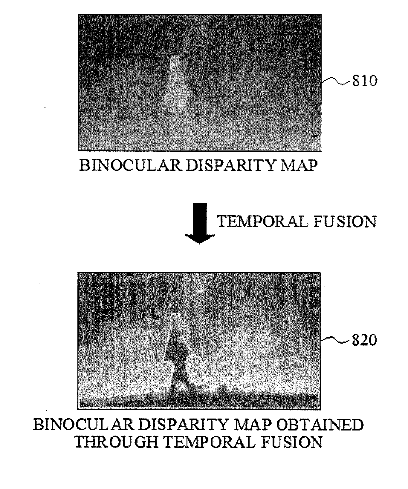
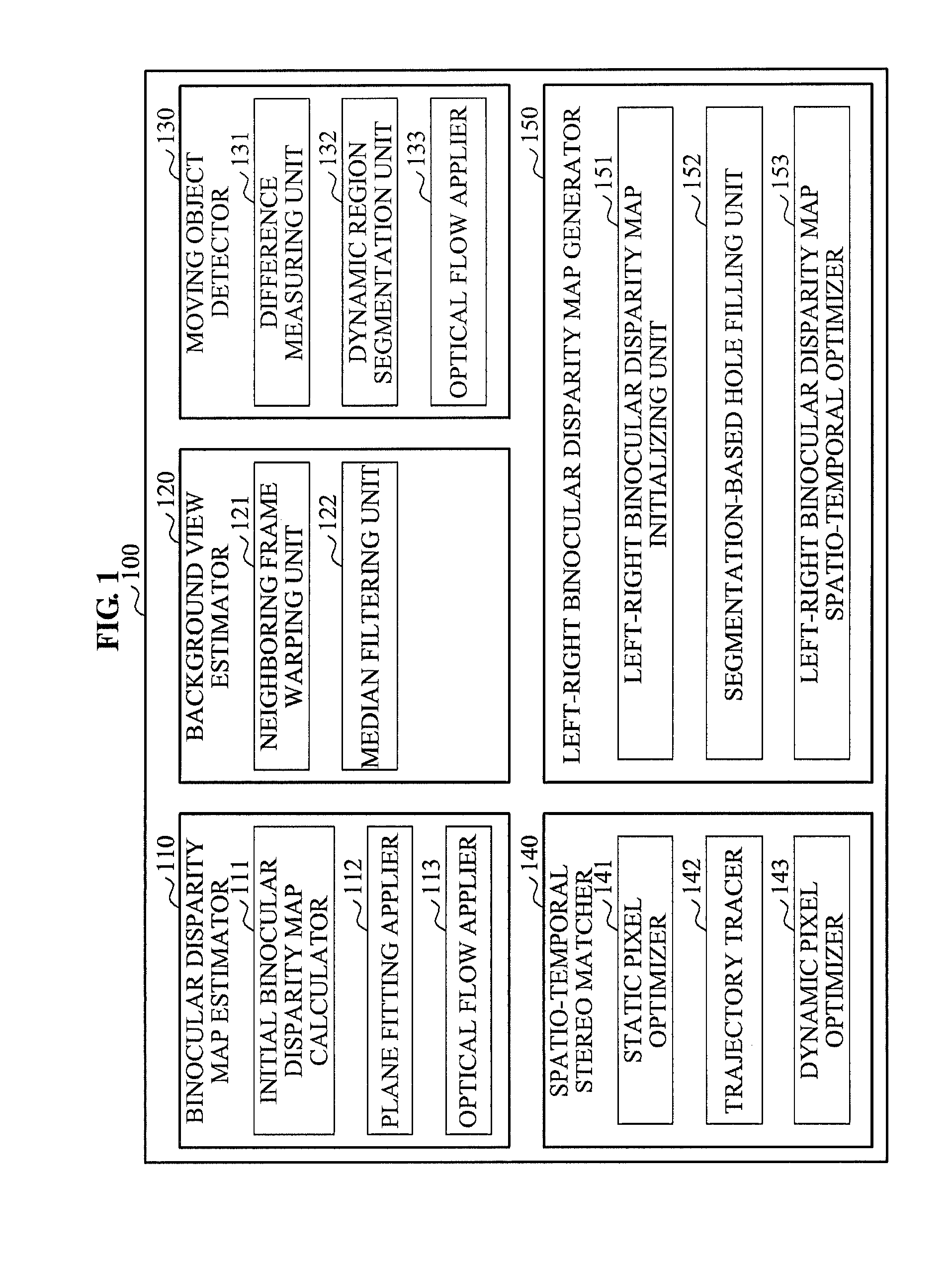
[0038]FIG. 1 illustrates a block diagram of an image processing apparatus 100 according to example embodiments.

[0039]The image processing apparatus 100 may include a binocular disparity map estimator 110, a background view estimator 120, a moving object detector 130, a spatio-temporal stereo matcher 140, and a left-right binocular disparity map generator 150.

[0040]The binocular disparity map estimator 110 may include an initial binocular disparity map calculator 111, a plane fitting applier 112, and an optical flow applier 113.

[0041]The background view estimator 120 may include a neighboring frame warping unit 121 and a median filtering unit 122.

[0042]The moving object detector 130 may include a differen...


PUM


Abstract

An image processing apparatus and method may estimate binocular disparity maps of middle views from among a plurality of views through use of images of the plurality of views. The image processing apparatus may detect a moving object from the middle views based on the binocular disparity maps of the frames. Pixels in the middle views may be separated into dynamic pixels and static pixels through detection of the moving object. The image processing apparatus may apply bundle optimization and a local three-dimensional (3D) line model-based temporal optimization to the middle views so as to enhance binocular disparity values of the static pixels and dynamic pixels.

Description

CROSS-REFERENCE TO RELATED APPLICATIONS[0001]This application claims the priority benefit of Korean Patent Application No. 10-2011-0127153, filed on Nov. 30, 2011, in the Korean Intellectual Property Office, the disclosure of which is incorporated herein by reference.BACKGROUND[0002]1. Field[0003]Example embodiments disclosed herein relate to a method and apparatus for recovering depth information of an image, and more particularly, to a method and apparatus for recovering a set of depth maps that may be spatio-temporally consistent, based on video sequences captured by a plurality of cameras.[0004]2. Description of the Related Art[0005]Recovering a depth image based on images or videos is a fundamental issue in the computer vision field. Recovering the depth image may be used for three-dimensional (3D) reconstruction, 3D film making, autonomous robotic navigation, video segmentation and editing, and the like.[0006]Through stereo-matching, depth information may be recovered based on...

Claims


Application Information

Patent Timeline
Patent Type & Authority Applications(United States)
IPC IPC(8): G06K9/00
CPCG06T2207/20144G06T2207/10021G06T7/2006G06T7/0077G06T7/194G06T7/215G06T7/596G06T7/20G06T15/00H04N13/00
Inventor KIM, JIWONZHANG, GUOFENGPARK, DU SIKLEE, HO YOUNGBAO, HUJUNYANG, WENZHUO
Owner SAMSUNG ELECTRONICS CO LTD
Why Eureka
Try Eureka