Developing device

a technology of developing sleeves and developing sleeves, applied in the field of developing sleeves, can solve the problems of reducing the feeding performance of developing sleeves, deformation of developing sleeves, and inability to achieve suitable image formation by using single developing sleeves, etc., and achieve the effect of reducing an image d

Inactive Publication Date: 2013-05-30
CANON KK
View PDF9 Cites 13 Cited by
  • Summary
  • Abstract
  • Description
  • Claims
  • Application Information

AI Technical Summary

Benefits of technology

[0010]A principal object of the present invention is to provide a developing device, in which development is made by using a plurality developer carrying members, capable of reducing an image defect generated due to overlapping, on an image, of pitch non-uniformity portions generated by grooves of the respective developer carrying members.

Problems solved by technology

The developing sleeve having the unevenness by using the sandblast was accompanied with a problem that an amount of unevenness becomes small when the surface is abroad by use of the developing sleeve and thus a developer feeding performance is lowered.
When the amount of unevenness is increased for enhancing the developer feeding performance, there is a need to effect blasting by hitting the developing sleeve surface by abrasive grain during machining, so that there arose a problem such that the developing sleeve is deformed.
However, in a stream of recent demands on speed-up of the copying machine, in the case where the rotation movement speed of the photosensitive drum became high, suitable image formation could not always be effected by using the single developing sleeve.
However, when the peripheral speed of the developing sleeve is increased, centrifugal force acting on the developer which forms a magnetic brush becomes large and thus a degree of scattering of the developer becomes large to cause contamination inside the copying machine, so that there is a possibility of a lowering in apparatus (device) function.
For this reason, an amount of a toner moved onto the photosensitive drum is changed between the groove region and the non-groove region, so that non-uniformity (banding) can occur on an output image with a groove pitch.

Method used


Image

  • Developing device
  • Developing device
  • Developing device

Examples


embodiment 1

Image Forming Apparatus

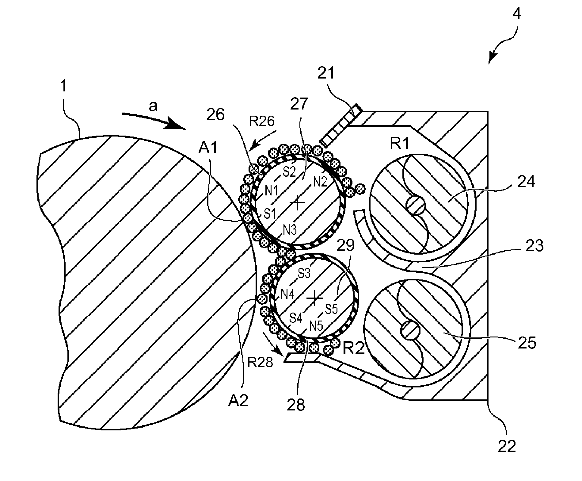
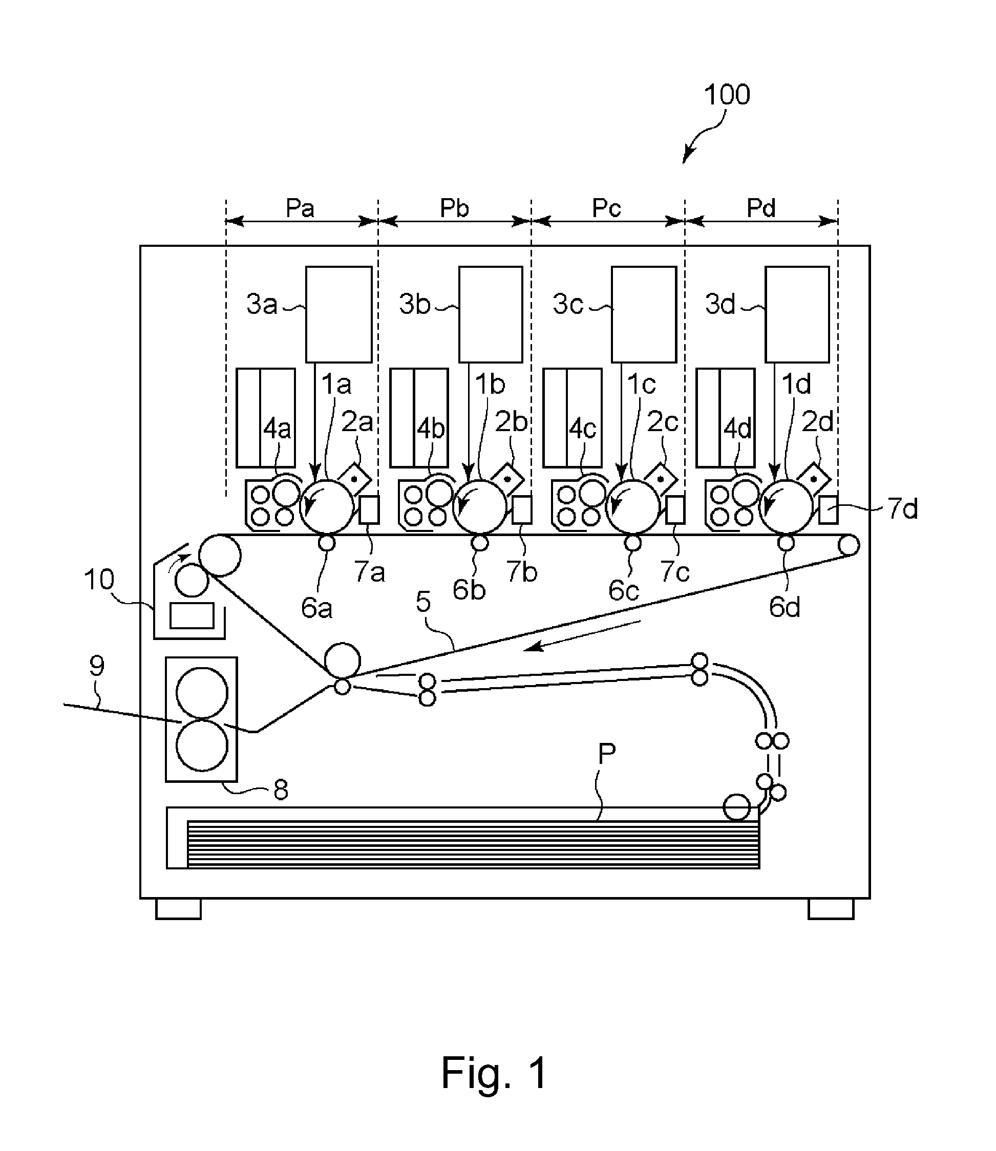
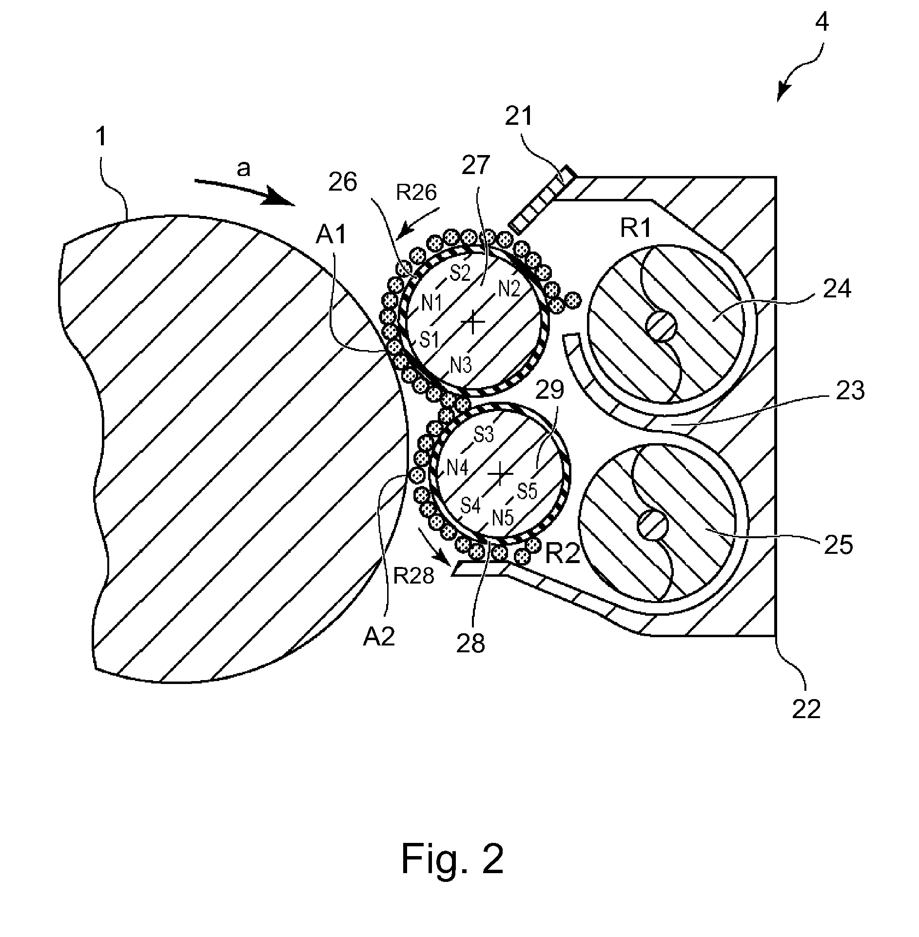
[0026]FIG. 1 is an illustration of a structure of an image forming apparatus. FIGS. 2 and 3 are illustrations of a structure of a developing device. As shown in FIG. 1, an image forming apparatus 100 is an intermediary transfer type full-color printer of the tandem type in which image forming portions Pa, Pb, Pc and Pd for different colors are provided along an intermediary transfer belt 5. Along the intermediary transfer belt 5 (intermediary transfer medium), together with a monochromatic image forming portion, a plurality of color (chromatic) image forming portions are disposed.

[0027]At the image forming portion Pa, a yellow toner image is formed on a photosensitive drum 1a as an image bearing member and then is primary-transferred onto the intermediary transfer belt 5. At the image forming portion Pb, a magenta toner image is formed on a photosensitive drum 1b and then is primary-transferred superposedly onto the yellow toner image on the intermediary trans...

embodiment 2

[0054]In the image forming apparatus described in Embodiment 1, in the case where the developing sleeves are changed in groove inclination, the developing sleeves are different in developer feeding property.

[0055]With respect to the feeding property of the groove-shaped sleeve, a (developer) feeding force acts on the grooves with respect to the thrust direction. In the case of the oblique line-like grooves, as shown in FIG. 6, when an angle formed between each groove and the thrust direction of the developing sleeve is θ (θa or θb), a feeding force corresponding to cos θ with respect to the vertical direction of the oblique line-like grooves acts in the sleeve rotational direction.

[0056]For this reason, the feeding force of the developing sleeve is changed when the inclination (angle) of the oblique line-like grooves is changed, and therefore an amount of the developer conveyed on the developing sleeve is changed. When the amount of the developer on the developing sleeve is changed,...

embodiment 3

[0064]The oblique line-like grooves has a feeding force in the axial (thrust) direction in addition to the sleeve rotational direction. For that reason, there can arise a possibility that the developer is liable to be localized in one side of the developing sleeve with respect to the thrust direction during the conveyance thereof on the developing sleeve. In Embodiment 1, both of the oblique line-like groove angles are 90 degrees or more but in that case, the thrust feeding directions of the developer on the respective developing sleeves becomes the same, so that the developer is more liable to be localized during the conveyance thereof on the two developing sleeves. When the developer is localized, there arises a possibility that the developer is leaked out to the outside of a feeding region at the sleeve end portion.

[0065]Therefore, in this embodiment, as shown in FIG. 8, oblique line-like groove angles of an upstream developing sleeve 26 provided in an upstream side and a downstr...


PUM


Abstract

A developing device includes first and second developer carrying members for developing an electrostatic latent image formed on an image bearing member. The first developer carrying member has a surface provided with grooves and feeds a developer carried thereon to a first developing region which is an opposing portion where the first developer carrying member opposes the image bearing member. The second developer carrying member carries the developer delivered from the first developer carrying member and feeds the developer to a second developing region which is an opposing portion where the second developer carrying member opposes the image bearing member. The second developer carrying member has a surface provided with grooves different in angle from those of the surface of the first developer carrying member.

Description

FIELD OF THE INVENTION AND RELATED ART[0001]The present invention relates to a developing device for developing an electrostatic latent image, formed on an image bearing member by an electrophotographic process, an electrostatic recording process or the like, to form a visible image. Particularly, the present invention relates to the developing device for developing the electrostatic latent image by a plurality of developer carrying members having a grooved surface.[0002]In an image forming apparatus such as a copying machine using the electrophotographic process, the developing device for visualizing the electrostatic latent image, formed on the image bearing member such as a photosensitive drum, by depositing a developer on the electrostatic latent image is provided. In such a developing device, a developing sleeve for carrying and feeding (conveying) the developer to a developing position where the developing sleeve opposes the photosensitive drum is provided. On a surface of som...

Claims


Application Information

Patent Timeline
Patent Type & Authority Applications(United States)
IPC IPC(8): G03G15/09
CPCG03G2215/0648G03G15/0928
Inventor SAKAMAKI, TOMOYUKI
Owner CANON KK
Why Eureka
Try Eureka