Radial turbine

a radial turbine and turbine technology, applied in the direction of machines/engines, stators, liquid fuel engines, etc., can solve the problems of decreasing the turbine efficiency, reduce the number of parts, suppress the decrease in the turbine efficiency of the radial turbine, and reduce the manufacturing cos

Active Publication Date: 2013-05-30
MITSUBISHI HEAVY IND LTD
View PDF21 Cites 21 Cited by
  • Summary
  • Abstract
  • Description
  • Claims
  • Application Information

AI Technical Summary

Benefits of technology

[0037]With the present invention, on a shroud side of the turbine wheel, a plurality of sub-inlets are formed at positions separated from the main inlet in the radial direction and the axial direction or a sub-pathway and a sub-inlet that branch from a hub surface of a main pathway and that extend toward the back face side of the main pathway are provided; therefore, rotational motive power can be extracted from fluids having a plurality of pressures by means of a single or integrated turbine wheel. Accordingly, the number of parts c

Problems solved by technology

In addition, because the two inlet flow channels are provided so as to be adjacent to each other simply by partitioning them with the partition wal

Method used


Image

  • Radial turbine
  • Radial turbine
  • Radial turbine

Examples


first embodiment

[0052]A radial turbine 100 according to a first embodiment of the present invention will be described below with reference to FIGS. 1 to 5.

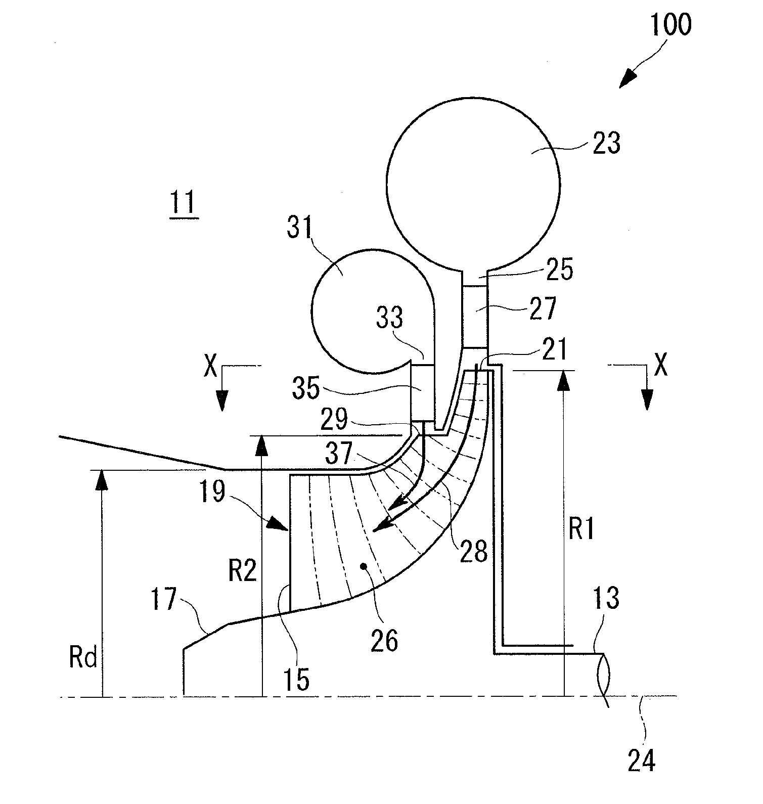
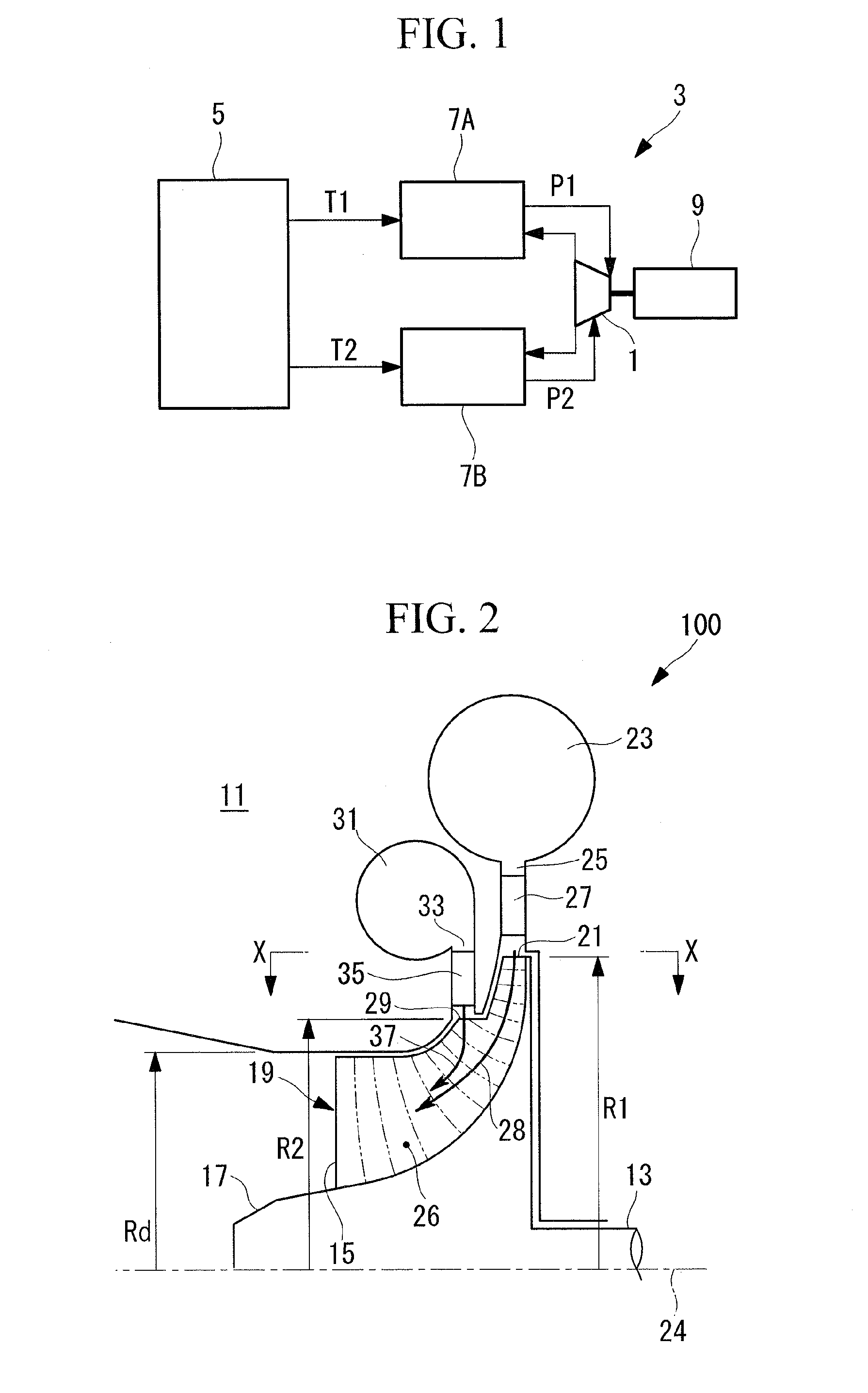
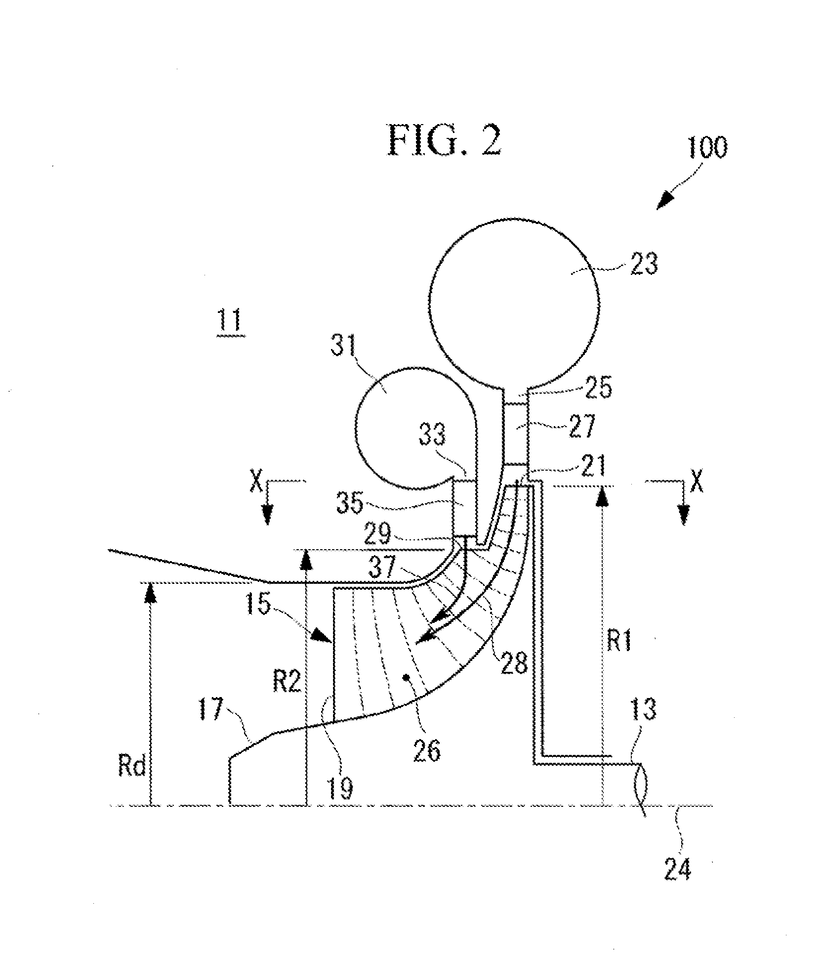
[0053]FIG. 1 is a block diagram showing the configuration of a binary power generation system employing an expansion turbine according to the first embodiment of the present invention. FIG. 2 is a partial sectional view showing the radial-turbine shape for the case in which a radial turbine of the present invention is employed as the expansion turbine in FIG. 1. FIG. 3 is a front view of a radial blade in FIG. 2 viewed in the axial direction. FIG. 4 is a diagram of the radial blade in FIG. 2 showing a view taken along X-X. FIG. 5 is a diagram showing a velocity triangle for a sub-inlet.

[0054]A binary power generation system 3 is, for example, a system used for geothermal power generation. The binary power generation system 3 is provided with a heat source unit 5 having a plurality of heat sources, two binary cycles 7A and 7B, an expansion turbine...

second embodiment

[0110]Next, a radial turbine 100 according to a second embodiment of the present invention will be described by using FIGS. 10 to 12.

[0111]Because this embodiment differs from the first embodiment in terms of the configuration of the turbine wheel, portions that are different will mainly be described here, and redundant descriptions for portions that are the same as those in the first embodiment described above will be omitted.

[0112]Note that, the same reference signs are assigned to members that are the same as those in the first embodiment.

[0113]FIG. 10 is a partial sectional view showing a radial turbine 100 according to the second embodiment of the present invention. FIG. 11 is a front view of a radial blade in FIG. 10 viewed in the axial direction. FIG. 12 is a diagram of the radial blade in FIG. 10 showing a view taken along Y-Y.

[0114]In this embodiment, a sub-pathway 32 that extends toward a back-face side is provided at a hub surface of the main pathway 26. Flows in the main...


PUM


Abstract

A radial turbine includes a radial turbine wheel provided with a main pathway in which blade height progressively increases while curving toward an axial direction from a radial direction. A sub-let is formed on a shroud side of the radial turbine wheel at a position separated from the main inlet in the radial direction and the axial direction. Also, a blade shape that forms the sub-inlet is such that, in a plane orthogonal to the axial line of the radial turbine wheel, a center line of the blade is inclined at a predetermined angle toward the rotation direction with respect to the radial direction.

Description

TECHNICAL FIELD[0001]The present invention relates to a radial turbine.BACKGROUND ART[0002]In a radial turbine provided with a single turbine wheel that converts the swirling energy of a flow of swirling fluid, which flows into the turbine wheel with a flow velocity component in the radial direction serving as the main component thereof, into rotational motive power and that expels the flow, whose energy has been released, in the axial direction thereof, the energy of a low / intermediate-temperature fluid and a high-temperature, high-pressure fluid is converted into rotational motive power; this kind of radial turbine has widely been employed for recovering motive power from discharge energy discharged from various industrial plants in the form of a high-temperature, high-pressure fluid, for recovering exhaust heat from systems that gain motive power via a thermal cycle of a motive-power source or the like in a ship or a vehicle, and for recovering motive power in binary-cycle power ...

Claims


Application Information

Patent Timeline
IPC IPC(8): F01D1/06
CPCF01D1/08F01D5/04F01D5/043F01D1/06F05D2210/43F05D2250/51F01D9/026
Inventor HIGASHIMORI, HIROTAKAKAWAMI, MASAYUKI
Owner MITSUBISHI HEAVY IND LTD
Why Eureka
Try Eureka