
System and Method for Determining Motion

Inactive Publication Date: 2013-05-30
AUCKLAND UNISERVICES LTD
View PDF2 Cites 32 Cited by
  • Summary
  • Abstract
  • Description
  • Claims
  • Application Information

AI Technical Summary

Benefits of technology

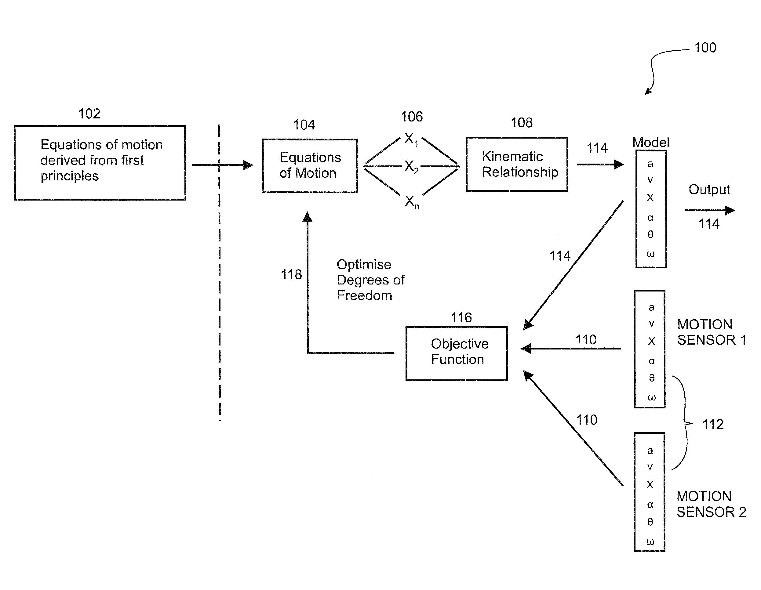
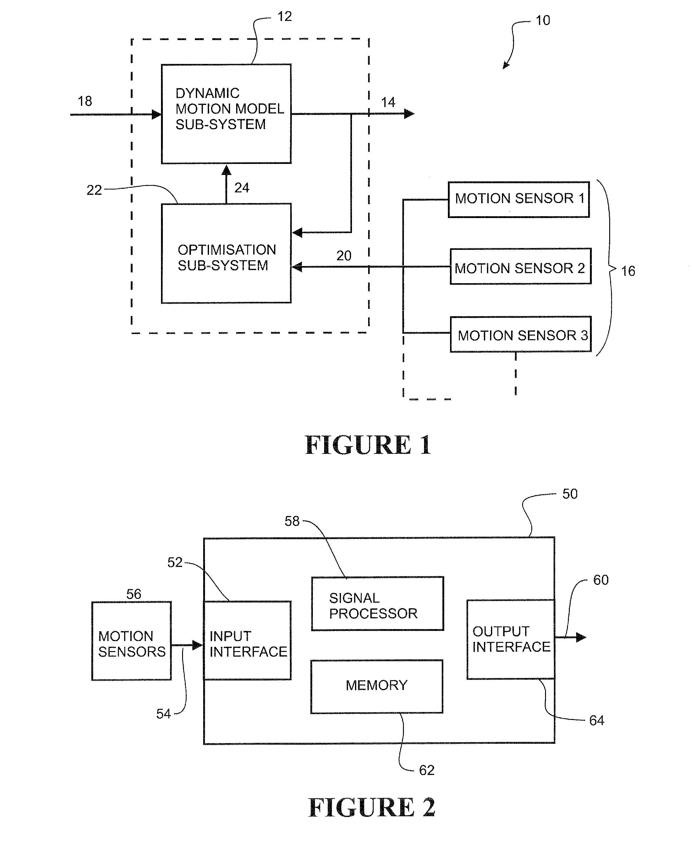
This patent describes a system and method for improving the accuracy of dynamic motion data by optimizing the system parameters of the dynamic motion model. This is done by applying an objective function to the stream of model motion data and sensed motion data to generate optimized system parameters, which reduces any error between the model motion data and sensed motion data. This results in a more accurate model motion data.

Problems solved by technology

They are often an attractive alternative to optically-based systems, which are expensive, susceptible to marker occlusion, and have limited capture areas.
However, current inertia-based motion capture systems are often bulky and inaccurate.
Accuracy issues arise, particularly when calculating displacement.
However, simple integration of the accelerations and rotational velocities compounds errors, causing the predicted position of the sensor to drift from its true value.

Method used


Image

  • System and Method for Determining Motion
  • System and Method for Determining Motion
  • System and Method for Determining Motion

Examples


experimental example

Swinging Pendulum

[0114]With reference to FIGS. 4a-7b, an experiment showing the implementation of the motion sensing system and method for a physical system comprising an instrumented two-dimensional pendulum will be described. The example is not intended to be limiting.

[0115]Referring to FIG. 4a, a simple pendulum was constructed consisting of a lightweight aluminum rod 200 mounted to a rotary encoder 202 (pendulum joint) and a brass mass 204 fastened to the bottom of the rod. A single motion sensor was placed at a selected position on the pendulum arm (measured distance of 0.534 m from the pivot) and aligned with the axis of the arm. The rotary encoder 202 had a 0.25° (0.00436 rad) resolution, and a sampling frequency of 100 Hz. FIG. 4b shows a schematic diagram illustrating the angle and acceleration components measured in the experiment, in particular tangential acceleration at, normal acceleration an, and angular position θ.

[0116]In this experiment, the motion sensor was an ind...

experiment observations

[0125]Validation is an important issue when using models to approximate parameter values in real world systems. The validation process requires the outputs of the system to be compared to physically measureable metrics. The results shown in this experiment validate both the model developed and the technology used.

[0126]The optimized output for lsens of 0.531 m was close to the physically measured length of 0.534 m. This shows us that the model was able to predict the position of the motion sensor within 1% of the physical measurement.

[0127]The accuracy of the model with respect to the sensor technology is shown in the comparison of the magnitude of the RMS errors between each of the parameters in the objective function. The fitted models all produce modest RMS errors. Further validation of the system comes from comparing both the raw sensor data and the optimized model to the ‘gold standardencoder. As shown an improvement in accuracy is gained from using the model in conjunction w...


PUM


Abstract

A method of generating model motion data representing the predicted motion of a physical system based on sensed motion data from one or more motion sensors within the physical system. The method generates a stream of model motion data representing the predicted motion of the physical system based on a dynamic motion model of the physical system based on initial estimates of system parameters. The method then optimizes the system parameters of the dynamic motion model based on processing of the streams of model motion data and sensed motion data from one or more motion sensors within the physical system.

Description

FIELD OF THE INVENTION[0001]The present invention relates to a system and method for determining motion of a physical system. In particular, although not exclusively, the system and method is may be applied to determining the motion of mechanical, electro-mechanical, and / or biomechanical systems, including human joint and / or limb movement.BACKGROUND TO THE INVENTION[0002]Inertial motion capture systems are becoming increasingly prominent in today's market. They are often an attractive alternative to optically-based systems, which are expensive, susceptible to marker occlusion, and have limited capture areas. However, current inertia-based motion capture systems are often bulky and inaccurate.[0003]Accuracy issues arise, particularly when calculating displacement. Inertial measurement units (IMU) typically output linear acceleration and rotational velocities which, when integrated, can provide estimates of linear displacement and angle, respectively. However, simple integration of th...

Claims


Application Information

Patent Timeline
IPC IPC(8): G06F17/50
CPCG06F17/5009A63B2024/0015A63B24/0006G06F30/20
Inventor FINCH, MARK CHRISTOPHERLINTERN, THOMAS OLIVERNIELSEN, POULTABERNER, ANDREW JAMES
Owner AUCKLAND UNISERVICES LTD
Learn More