Battery mounting apparatus for electric vehicle, battery unit transfer apparatus for electric vehicle, and method for mounting battery unit

a technology for electric vehicles and battery units, applied in the direction of cell components, propulsion by batteries/cells, cell component details, etc., can solve the problems of reducing the likelihood of the battery unit receiving an excessive load, etc., and achieve the effect of ensuring the durability of the battery uni

Active Publication Date: 2013-06-06
TOYOTA IND CORP
View PDF1 Cites 19 Cited by
  • Summary
  • Abstract
  • Description
  • Claims
  • Application Information

AI Technical Summary

Benefits of technology

[0008]Accordingly, it is an objective of the present invention to provide a battery unit mounting apparatus for an electric vehicle that is capable of properly mounting a battery unit to the bottom of a vehicle body, while ensuring the durability of the battery unit.

Problems solved by technology

In other words, the battery unit is likely to receive an excessive load as a whole, which may degrade the durability of the battery unit.

Method used


Image

  • Battery mounting apparatus for electric vehicle, battery unit transfer apparatus for electric vehicle, and method for mounting battery unit
  • Battery mounting apparatus for electric vehicle, battery unit transfer apparatus for electric vehicle, and method for mounting battery unit
  • Battery mounting apparatus for electric vehicle, battery unit transfer apparatus for electric vehicle, and method for mounting battery unit

Examples


first embodiment

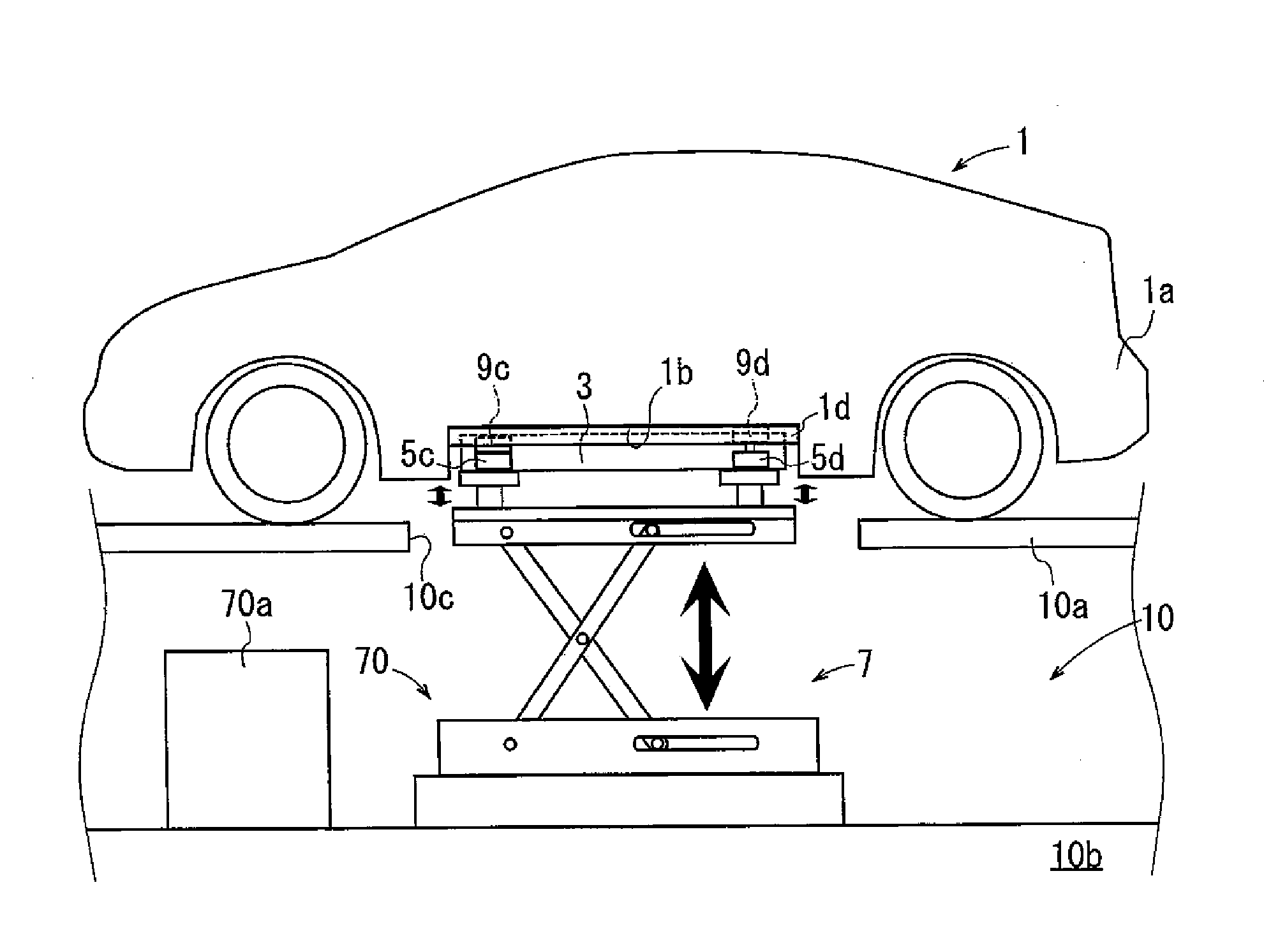
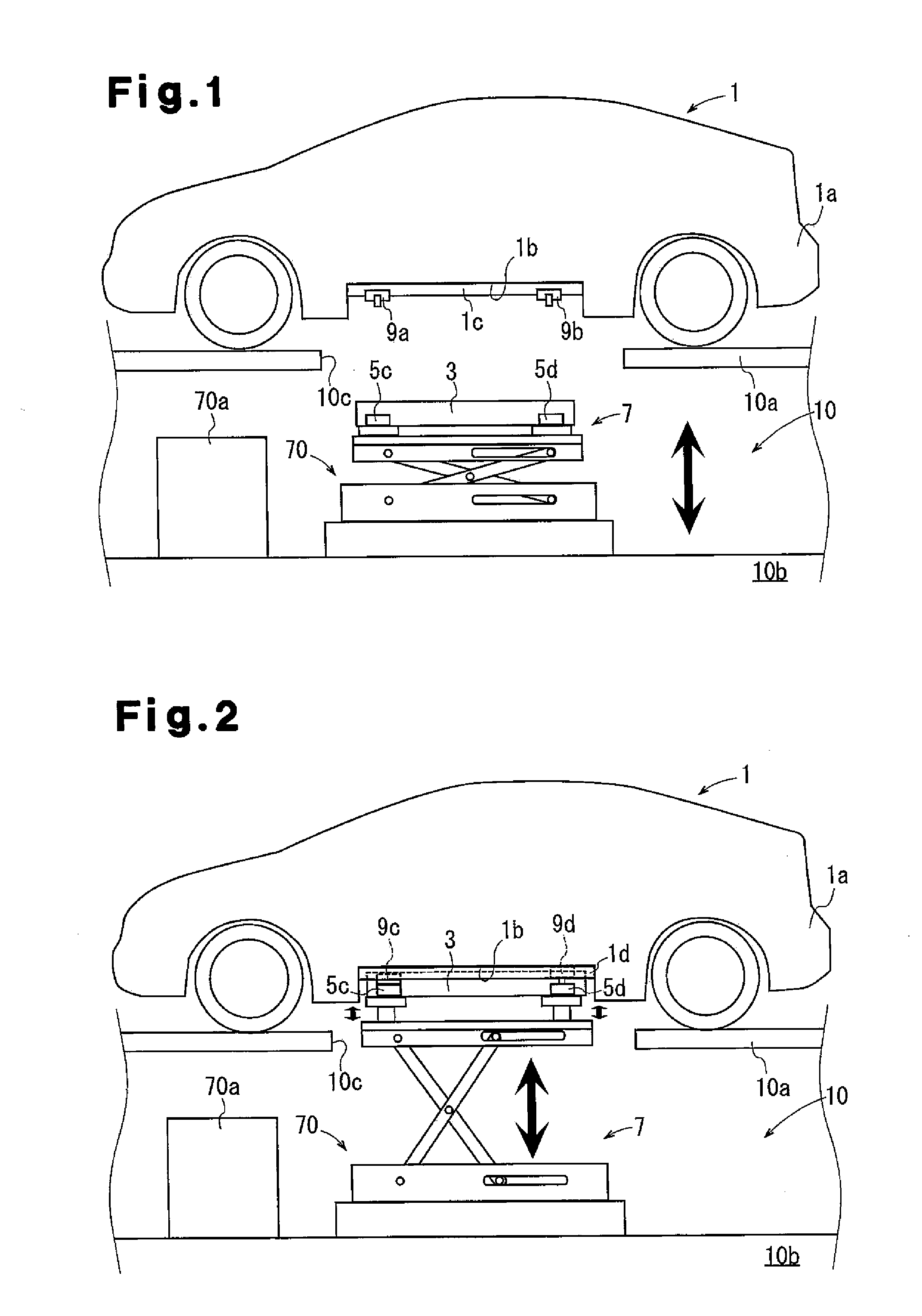
[0026]As shown in FIGS. 1 and 2, a battery unit mounting apparatus according to the first embodiment is designed for an electric vehicle 1. The electric vehicle 1 has a mounting space 1b for mounting a battery unit 3 in a lower portion of a vehicle body 1a. The vehicle body 1a has frames 1c, 1d, which are located on the right and left sides of the vehicle body 1a and extend in the front-rear direction. The frames 1c, 1d form side edges of the mounting space 1b. FIG. 1 shows the frame 1c, which is located on the right side of the vehicle body 1a, and FIG. 2 shows the frame 1d, which is located on the left side of the vehicle body 1a.

[0027]When the storage amount of the battery unit 3 is reduced due to travel of the vehicle 1, the battery unit mounting apparatus removes the battery unit 3 from the vehicle body 1a and replaces it with a charged battery unit 3.

[0028]Replacement of the battery unit 3, or a process for mounting the battery unit 3, is performed on a battery replacement st...

second embodiment

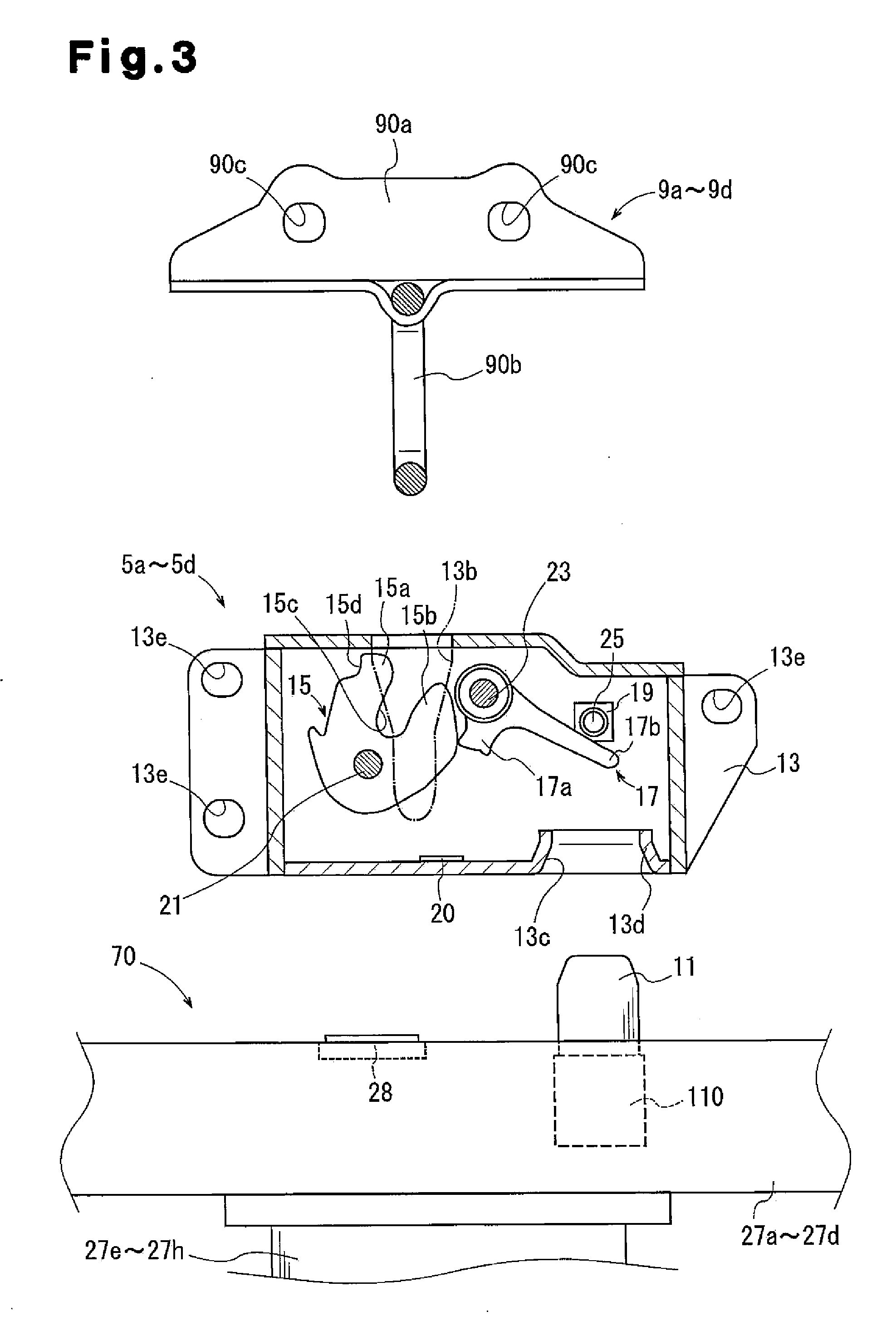
[0084]A transfer apparatus 7 according to a second embodiment includes a transfer apparatus main body 71 and a control unit 70a. The transfer apparatus main body 71 has an individual stage 27d and an individual stage 27i on a support table 26 a shown in FIG. 8. The individual stage 27i is capable of supporting from below the lock devices 5a to 5c, which belong to the first engagement group. That is, the individual stage 27i forms a first group stage.

[0085]Although not illustrated, the individual stage 27i is connected to the telescopic rods 27e to 27g on its back side, or the lower side. The number of telescopic rods connected to the individual stage 27i may be changed as necessary in accordance with the center of gravity of the battery unit 3 as well as the weight of the battery unit 3.

[0086]Pins 11 and limit switches 28 are provided on the surface of the individual stage 27i at positions corresponding to the lock devices 5a to 5c. The other structures of the transfer apparatus mai...


PUM

PropertyMeasurementUnit
timeaaaaaaaaaa
heightaaaaaaaaaa
heightsaaaaaaaaaa

Abstract

A battery unit mounting apparatus for an electric vehicle includes four or more fixing portions configured to be provided at the bottom of an electric vehicle and four or more corresponding portions-to-be-fixed on a battery unit. When the battery unit is raised toward the vehicle, the battery unit mounting apparatus causes each fixing portion to be engaged with the corresponding one of the portions-to-be-fixed. There is a first group, formed by three of the fixing portions and corresponding three of the portions-to-be-fixed, and a second group, formed by the remaining one or more of the fixing portions and the remaining one or more of the portions-to-be-fixed. The fixing portion and the portion-to-be-fixed in the second group are configured to be engaged with each other after the fixing portions and the portions-to-be-fixed in the first group are engaged.

Description

BACKGROUND OF THE INVENTION[0001]The present invention relates to a battery unit mounting apparatus for an electric vehicle, a battery unit transfer apparatus used with the battery unit mounting device, and a method for mounting a battery unit.[0002]Japanese Laid-Open Patent Publication No. 2010-173364 discloses a conventional battery unit transfer apparatus. The battery unit transfer apparatus includes a lift actuator for raising a polyhedron jig from below an electric vehicle, a battery fixing means for fixing a battery unit on the polyhedron jig, and an inclination adjusting means.[0003]In the battery unit transfer apparatus, the battery fixing means fixes a battery unit on the polyhedron jig, and the lift actuator raises the polyhedron jig. The inclination adjusting means then rotates the polyhedron jig, thereby adjusting the inclination of the battery fixing means. Accordingly, the bottom of the body of the electric vehicle and the battery unit on the polyhedron jig become para...

Claims


Application Information

Patent Timeline
Patent Type & Authority Applications(United States)
IPC IPC(8): B60S5/06B60K1/04B60L50/64
CPCB60S5/06B60K1/04Y10T29/49002Y02T90/124Y10T29/5313H01M2/1083B60L53/80Y02T10/70Y02T10/7072Y02E60/10H01M50/204H01M50/249B60L50/64H01M50/244B65G67/00H02J7/00Y02T90/12
Inventor OJIMA, YOSHIOFUKAGAWA, TAKAHIROMURASE, TAKASHI
Owner TOYOTA IND CORP
Why Eureka
Try Eureka