

Suspension system for motor vehicles
a suspension system and motor vehicle technology, applied in the direction of shock absorbers, fluid couplings, transportation items, etc., can solve the problems of reservoir maintenance, constant monitoring, and hydrostatic lines needed for forward and reverse flow
- Summary
- Abstract
- Description
- Claims
- Application Information
AI Technical Summary
Benefits of technology
Problems solved by technology
Method used
Image

Examples
Embodiment Construction
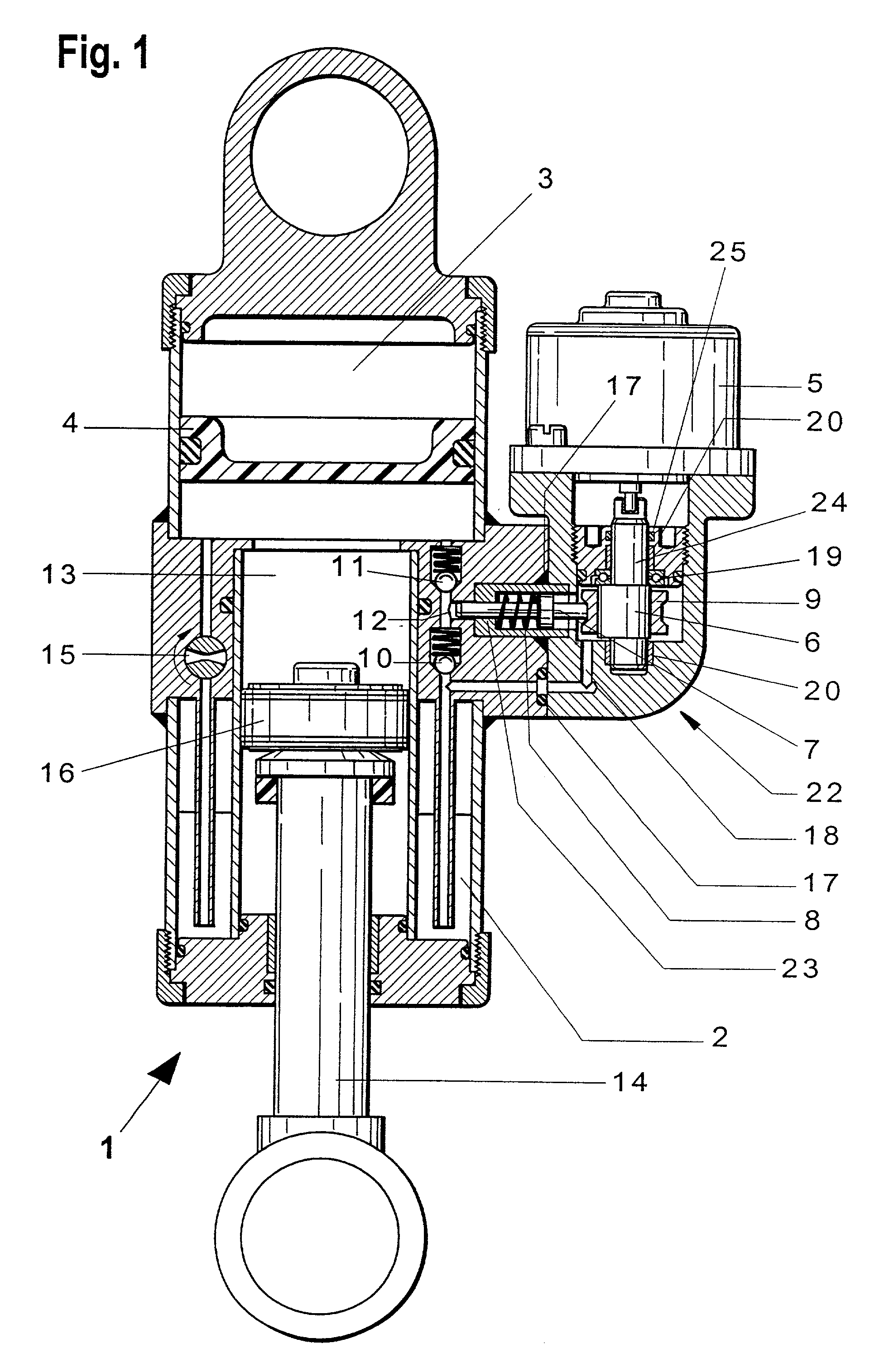
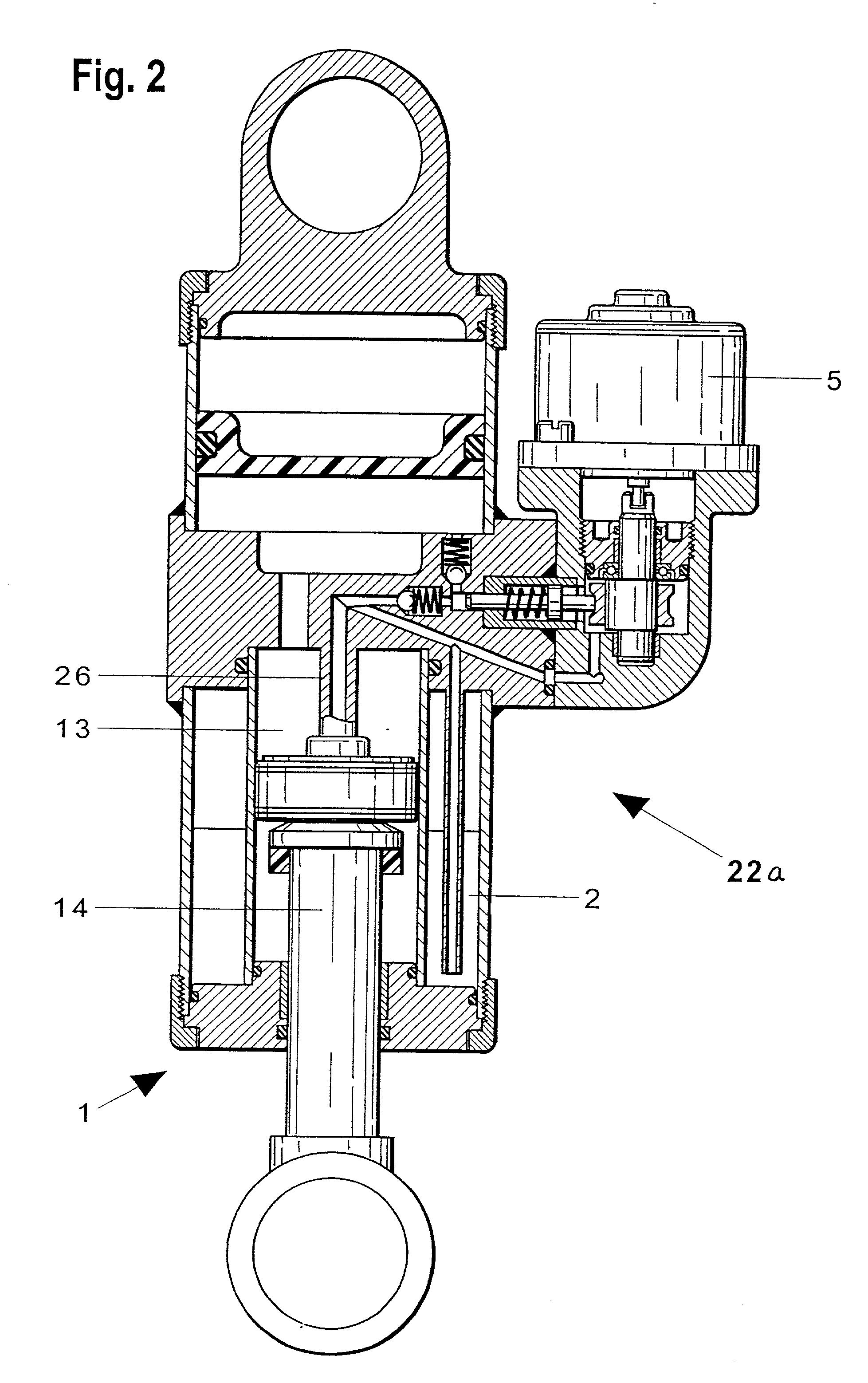
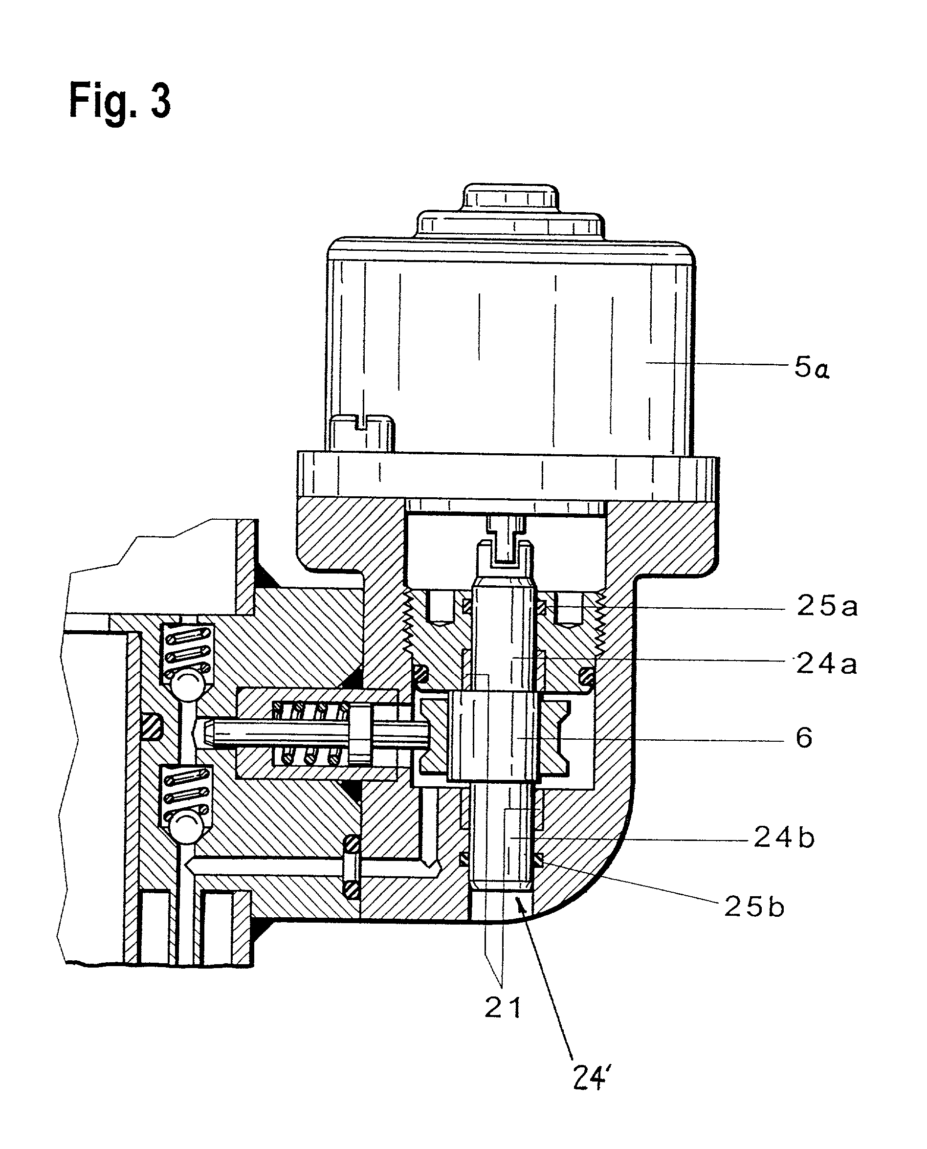
[0023] FIG. 1 shows a piston-cylinder unit 1 according to an embodiment of the present invention in which an oil reservoir 2 and a pneumatic or gas spring volume 3 are integrated. Oil and gas are separated from each other in the gas spring volume 3 by a separating element 4 which is movable in a longitudinal direction of the piston cylinder unit 1. A drive unit 5 is connected to an oil pump 22 which is connected between the oil reservoir 2 and a high pressure area 13 of the piston-cylinder unit 1. When the drive unit 5 is switched on, a pump piston 7 of the oil pump 22 is set in reciprocating axial movement by the rotating movement of a cam 6. A restoring force is exerted on the pump piston 7 via a spring 8. A sliding ring 9 which reduces the point load of the pump piston 7 to a more favorable, i.e., larger, pressure area is associated with the cam 6. Therefore, the cam 6 rotates inside the fixed sliding ring 9.
[0024] Oil from the oil reservoir 2 is delivered from the pump space 12 ...
PUM
 Abstract
Description
Claims
Application Information