
Position shift control apparatus ensuring durability and operation accuracy thereof

a technology of position shift control and durability, which is applied in the direction of motor/generator/converter stopper, dynamo-electric converter control, instruments, etc., can solve the problems of reducing the accuracy of operating the range shift mechanism, the backlash or play of the torque transmission mechanism, and the speed reducer having the backlash between the gears installed therein, so as to ensure the durability and operation accuracy of the position shift control apparatus. , the effect of reducing the mechanical load

Inactive Publication Date: 2008-01-03
DENSO CORP +1
View PDF28 Cites 18 Cited by
  • Summary
  • Abstract
  • Description
  • Claims
  • Application Information

AI Technical Summary

Benefits of technology

[0012] It is another object of the invention to provide a position shift control apparatus designed to minimize the number of control operations exerting a mechanical load on, for example, a detent mechanism or parts of a torque transmission mechanism, and compensates for an error in shifting the position of an object which arises from backlash or play in the torque transmission mechanism to ensure the durability and controllability of the apparatus.
[0015] When the torque created by the elastic pressure produced by the detent mechanism is opposite in orientation to that outputted by the motor, it will cause the backlash or play in the torque transmission mechanism to be minimized. Therefore, when such a condition is encountered, it becomes possible to learn the value of the angular position of the motor as the reference angular position of the motor free from the backlash or play in the torque transmission mechanism. The use of such a reference angular position in moving the motor to the target position minimizes the mechanical load on the detent mechanism or parts of the torque transmission mechanism and ensures the durability and operation accuracy of the position shift control apparatus.

Problems solved by technology

The torque transmission mechanism usually has mechanical backlash or play.
For instance, the speed reducer has the backlash between gears installed therein.
The mechanical backlash or play in the torque transmission mechanism will result in an inevitable error in controlling the angular position of the output shaft (i.e., the manipulated variable in the range shift mechanism) based on the count value of the encoder, thus leading to a decrease in accuracy of operating the range shift mechanism.
The motor control system, as taught in Publication No. 2004-308752, requires the execution of the initial motor drive operation every start-up of the system, thus resulting in an increase in mechanical load on the detent mechanism or parts of the torque transmission mechanism, which leads to a greater concern about the durability thereof.
The system, however, does not compensate for an error in learning the reference angular position at all which arises from the angle at which the NSW is mounted on the automatic transmission.
Further, when the NWS is changed from the off-state to the on-state, torque which is created by elastic pressure, as produced by the detent mechanism, and acts on the output shaft of the motor is identical in orientation with that outputted by the motor, thus resulting in a difficulty in knowing whether the amount of backlash or play in the torque transmission mechanism is increasing or decreasing during the rotation of the motor.
This also results in an additional error in learning the reference angular position of the motor.

Method used


Image

  • Position shift control apparatus ensuring durability and operation accuracy thereof
  • Position shift control apparatus ensuring durability and operation accuracy thereof
  • Position shift control apparatus ensuring durability and operation accuracy thereof

Examples


Embodiment Construction

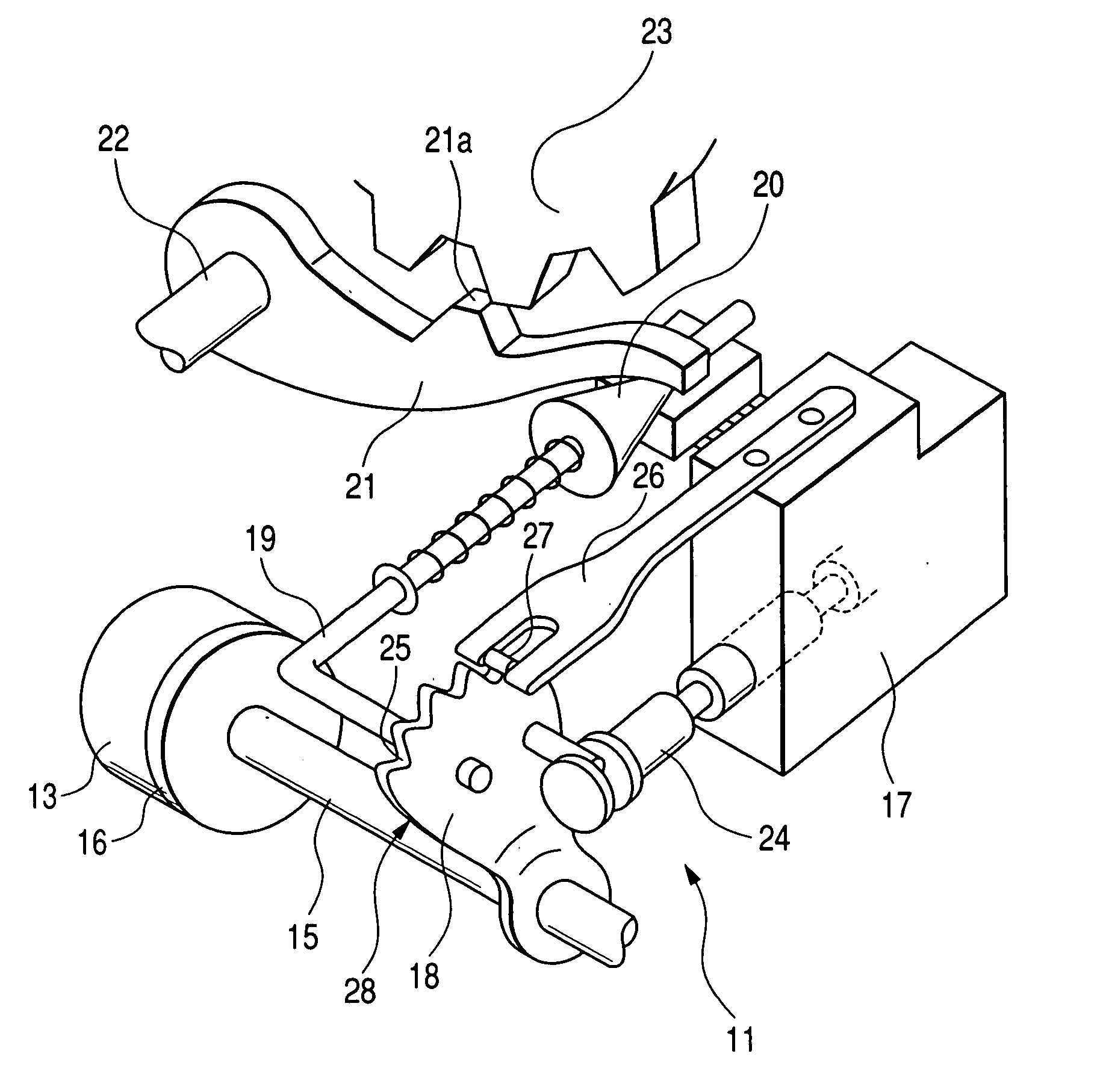
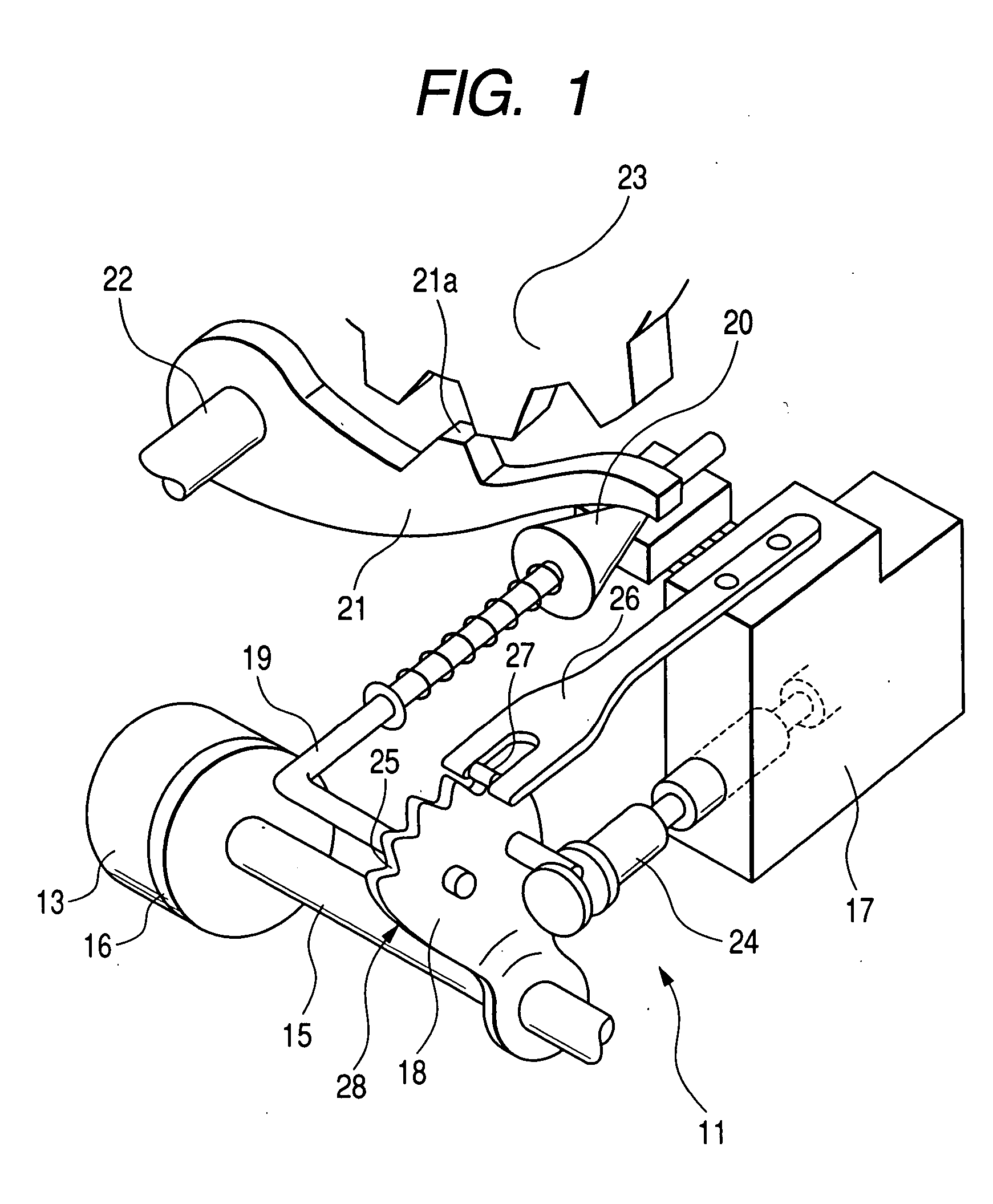
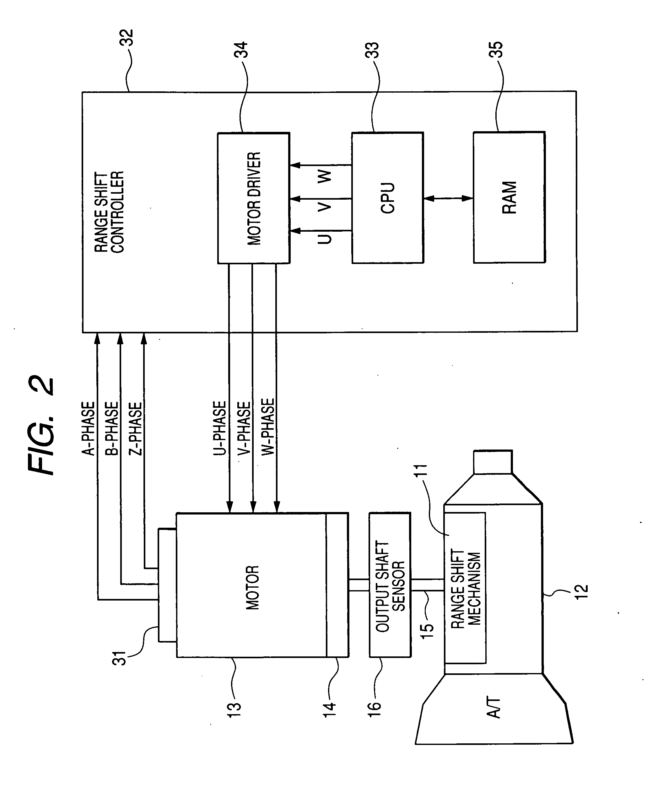
[0034] Referring to the drawings, wherein like reference numbers refer to like parts in several views, particularly to FIGS. 1 and 2, there is shown a range shift controller 32 according to the invention which is designed to control an operation of a range shift mechanism 11 installed in an automatic transmission 12 for automotive vehicles.

[0035] The range shift mechanism 11 works to change the gear of the automatic transmission 12. The automatic transmission 12, as referred to therein, has a typical structure which is designed to be switchable in operation between four gear ranges: a parking (P), range, a reverse (R) range, a neutral (N) range, a drive (D) range, and a low (L) range. The range shift mechanism 11 is used to shift the P, R, N, D, and L ranges of the automatic transmission 12 from one to another. The range shift mechanism 11 is driven by an electric motor 13. The synchronous motor 13 is made of a synchronous motor such as a switched reluctance motor (SRM) and has a s...


PUM


Abstract

A position shift control apparatus is provided which includes an electrical motor joined to an object through an output shaft and a torque transmission mechanism, a detent mechanism producing elastic pressure to hold the object at a target position, and a motor controller. When torque, which is created by the elastic pressure produced by the detent mechanism and acts on the output shaft during rotation of the motor, is opposite in orientation to that outputted by the motor, the motor controller determines the angular position of the motor, as sampled upon a change in an output from an output shaft position sensor, as a reference angular position of the motor for use in controlling the position of the motor, thereby resulting in a decrease in mechanical load on the detent mechanism and the torque transmission mechanism to ensure the durability and operation accuracy of the apparatus.

Description

CROSS REFERENCE TO RELATED DOCUMENT [0001] The present application claims the benefit of Japanese Patent Application No. 2006-164397 filed on Jun. 14, 2006, the disclosure of which is incorporated herein by reference. BACKGROUND OF THE INVENTION [0002] 1. Technical Field of the Invention [0003] The present invention relates generally to a position shift control apparatus designed to shift the position of an object joined to an output shaft connected to an electric motor through a torque transmission mechanism such as a speed reducer. [0004] 2. Background Art [0005] In recent years, there has been an increasing tendency in automotive vehicles to replace mechanical drive systems with electrical ones equipped with an electrical motor for meeting requirements of space saving-designs or improvement of assemblability and controllability thereof. For example, Japanese Patent First Publication No. 2004-23890 (US 2006 / 0033464 A1) discloses an example of the electrical drive system designed t...

Claims


Application Information

Patent Timeline
Patent Type & Authority Applications(United States)
IPC IPC(8): G05B1/06H02P8/00H02P8/06
CPCF16H61/32F16H2061/283Y10T477/653Y10T74/19251Y10T477/688F16H2061/326
Inventor HORI, MASASHIMATSUZAKI, HARUKIKASHIWAGI, TOMOYUKISHINOJIMA, MASAAKI
Owner DENSO CORP
Learn More