Gas-turbine engine combustor

Inactive Publication Date: 2005-05-03
HONDA MOTOR CO LTD
View PDF13 Cites 17 Cited by
  • Summary
  • Abstract
  • Description
  • Claims
  • Application Information

AI Technical Summary

Benefits of technology

[0007]An object of the present invention is therefore to overcome the foregoing shortcomings by providing a gas-turbine engine combustor that enables to

Problems solved by technology

However, when this kind of combustor is used for premixed combustion, since premixed combustion is less stable than diffusive combustion, if

Method used


Image

  • Gas-turbine engine combustor
  • Gas-turbine engine combustor
  • Gas-turbine engine combustor

Examples


Example

[0024]A gas-turbine engine combustor according to an embodiment of the present invention will now be explained with reference to the attached drawings.

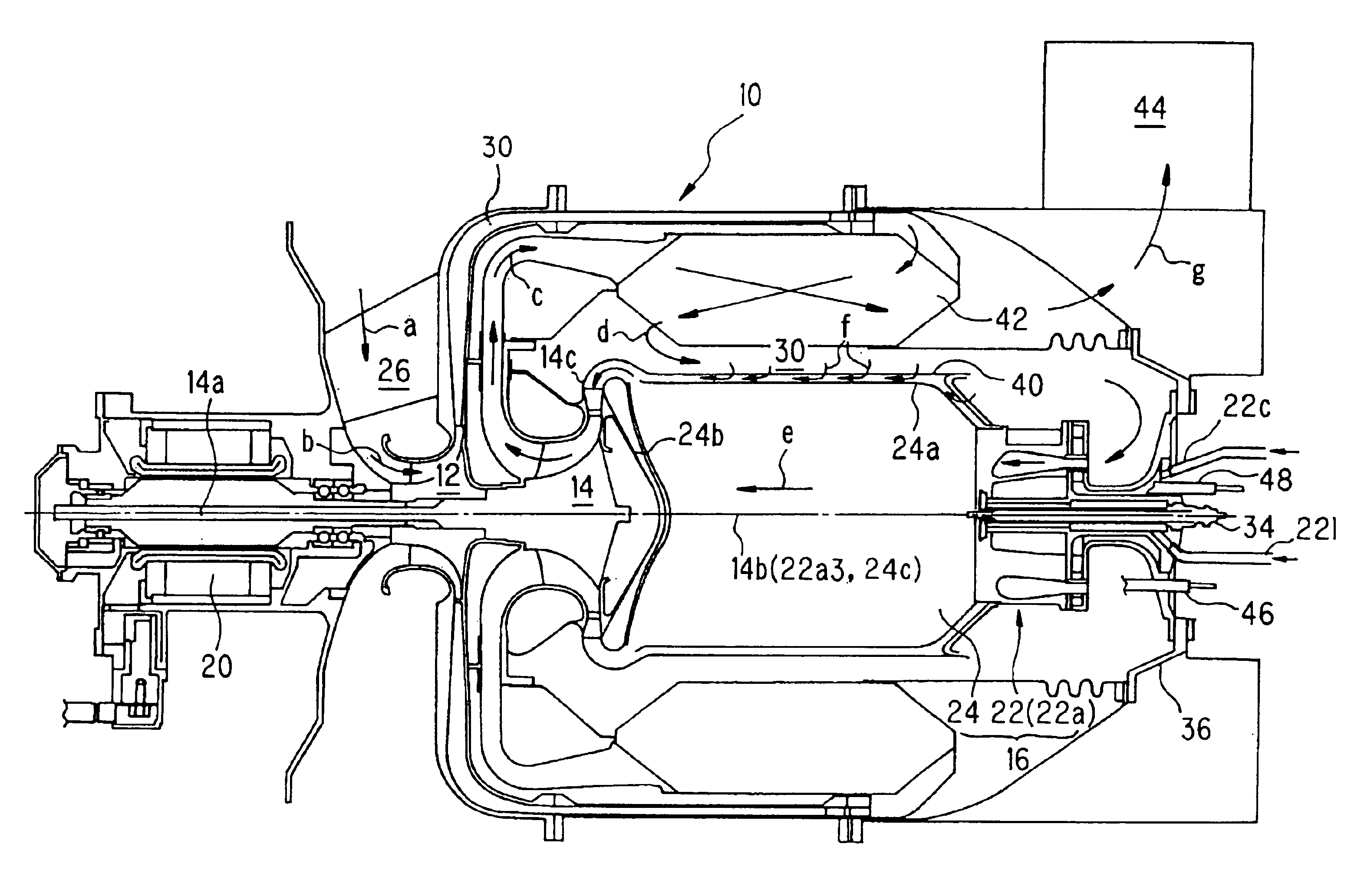
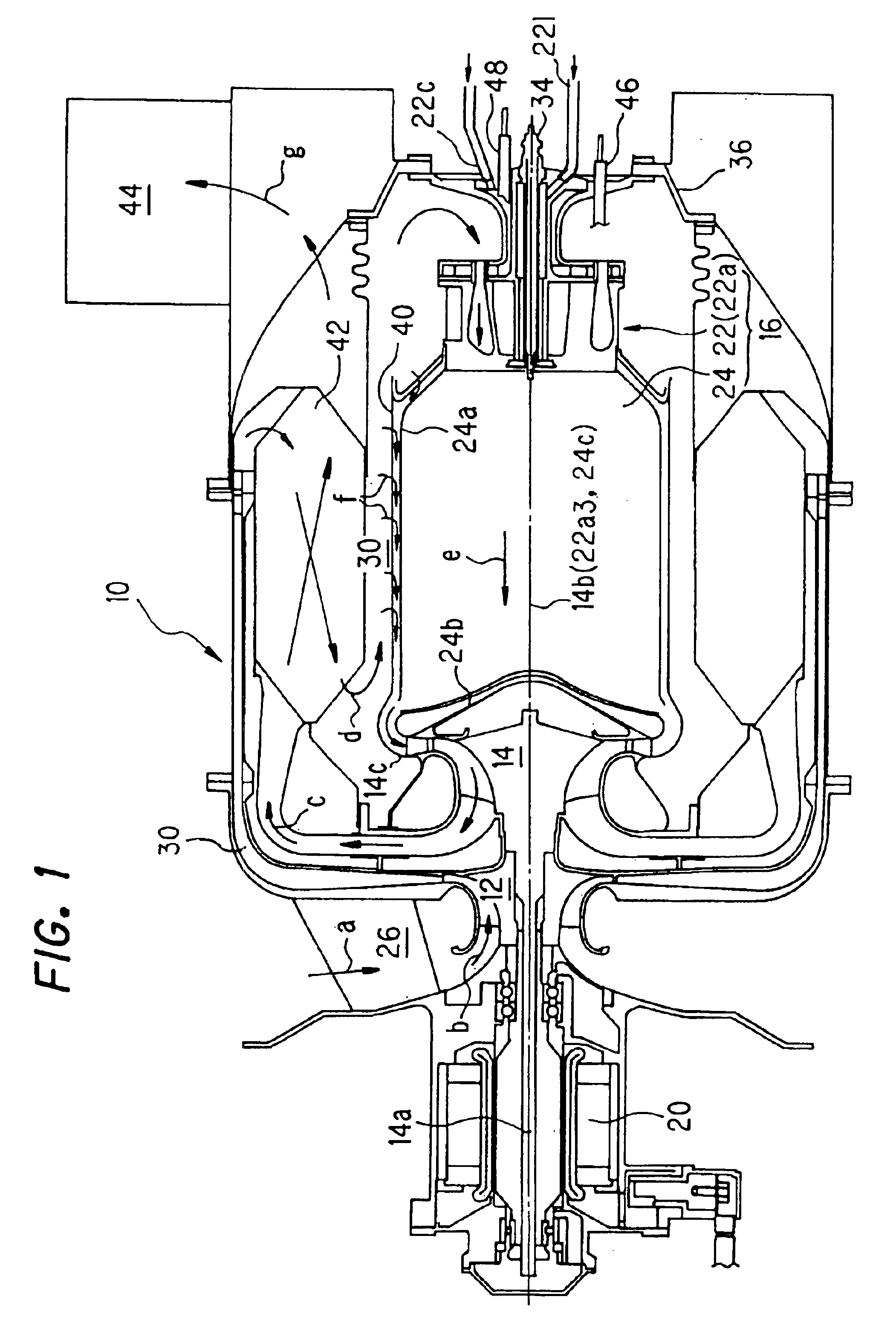
[0025]FIG. 1 is a schematic view showing the combustor together with the whole of the gas-turbine engine.

[0026]The gas-turbine engine is designated by reference numeral 10 in FIG. 1. The gas-turbine engine 10 is equipped with a compressor 12, a turbine 14 and a combustor 16. The compressor 12 is driven by rotation of the turbine 14 transmitted through an output shaft (turbine shaft) 14a of the turbine 14 that connects the two.

[0027]The output shaft 14a of the turbine 14 is also connected to a generator 20. The generator 20 is driven by the turbine 14 to generate around 100 kW of electricity. Electrical equipments (not shown) is connected to the generator 20 as a load. The gas-turbine engine 10 is a small unit for stationary installation in an independent power plant, i.e., the so-called micro turbine power generation system.

[0028]The ...


PUM


Abstract

A gas-turbine engine combustor having a plurality of venturi mixers, each connected to an air supply path that passes air compressed by a compressor and to a supply source of gaseous fuel, which mix the air and the gaseous fuel to produce an air-fuel mixture and supply the air-fuel mixture to a combustion chamber for generating premixed combustion or diffusive combustion such that produced combustion gas is supplied to a turbine through a turbine nozzle to rotates the turbine that outputs its rotation through an output shaft, while driving the compressor by the rotation. The combustor includes a casing which defines the combustion chamber, and a liner disposed at an outer side of the casing to be communicated with the turbine nozzle, wherein the liner is formed with a plurality of holes through which a part of air passing through the air supply path enters the outer side of the casing, thereby enabling to cool the combustion chamber casing effectively, without introducing a flesh air or a diluted air into the combustion section of the combustion chamber, while ensuring the strength and durability of the combustion chamber casing.

Description

BACKGROUND OF THE INVENTION[0001]1. Field of the Invention[0002]This invention relates to a gas-turbine engine combustor.[0003]2. Description of the Related Art[0004]Since the gas-turbine combustor is suffered from hot combustion gas, Japanese Laid-Open Patent Application No. Hei 10-68523 discloses cooling the combustion chamber liner (inner liner) by combining impingement cooling and film cooling with the use of a perforated liner as the inner liner and a similarly perforated liner faced to the inner liner.[0005]Specifically, in this prior art, the air used as the impingement cooling is also used as the film cooling, and the cooling air is finally introduced in to a combustion section in the combustion chamber where gas under combustion exists. Thus, this prior art proposes improving cooling by combining the impingement cooling and the film cooling.[0006]In the gas-turbine engine combustor, as mentioned in this prior art reference, a part of sucked air is normally used to dilute he...

Claims


Application Information

Patent Timeline
IPC IPC(8): F23R3/28F23R3/00F02C7/18F23R3/42
CPCF23R3/286F23R3/00F23D2900/00008F23R2900/03044
Inventor INOUE, TSUTOMUYAMAZAKI, ATSUSHI
Owner HONDA MOTOR CO LTD
Why Eureka
Try Eureka