Radiological image-capturing device, radiological image-capturing system, radiological image-capturing method, and program

a radiological image and camera technology, applied in the field of radiological image capture systems radiographic image capture methods, etc., can solve the problems of inability to electrically connect in view of safety, inability to synchronize image capture timings, and high installation and maintenance costs, and achieve the effect of appropriate captur

Active Publication Date: 2013-06-06
FUJIFILM CORP
View PDF4 Cites 50 Cited by
  • Summary
  • Abstract
  • Description
  • Claims
  • Application Information

AI Technical Summary

Benefits of technology

[0136]In the ninth aspect, the radiographic image can be more appropriately captured even if the user

Problems solved by technology

In this case, a manufacturer serviceman has to make the electrical connection between the control unit and the radiation apparatus at the system installation, resulting in high installation and maintenance costs.
In addition, in a case where the control unit and the radiation apparatus are obtained from different manufacturers, they often cannot be electrically connected in view of safety.
On the contrary, in a case where the control unit and the radiation apparatus are not electrically connected, the image capturing timings cannot be synchronized.
Therefore, in this case, the electronic cassette is excessively exposed even in a period in which the radiation is not emitted, whereby the resultant radiographic image has a high noise content.
Furthermore, the procedure of removing the unnecessary electric charges stored in the pixels cannot be ca

Method used


Image

  • Radiological image-capturing device, radiological image-capturing system, radiological image-capturing method, and program
  • Radiological image-capturing device, radiological image-capturing system, radiological image-capturing method, and program
  • Radiological image-capturing device, radiological image-capturing system, radiological image-capturing method, and program

Examples


modified example 1

[0313]In the above embodiment, even when the emission of the radiation 16 is judged to be started in the scan mode, the electronic cassette 20 is not switched into the exposure state until the one cycle is completed. The electronic cassette 20 may be switched into the exposure state immediately after the judgment of the emission of the radiation 16.

[0314]FIGS. 16 and 17 are diagrams for illustrating the electric charges in the pixels 102 in some rows in a case where the electronic cassette 20 is switched into the accumulation state after the radiation 16 is detected and then the one cycle of the scan mode is completed. In the scan mode, each of the gate drive circuits 150 reads the electric charges stored in the pixels 102 in the 0th to final rows sequentially row by row. In this case, for example, even if a digital value obtained by reading the electric charges stored in the pixels 102 in the 0th row is judged to be larger than the threshold value and thus the radiation 16 is detec...

modified example 2

[0325]In the above embodiment and Modified Example 1, the user operates the input unit 200 to input the number of images to be captured, and the image number setting part 224 in the system controller 24 sets the number of images to be captured and sends the number of images to the electronic cassette 20. The numbers of images may be recorded on the table 218 in association with the imaging areas and the diagnosis purposes. In this case, the image capturing condition setting part 222 reads from the table 218 the number of images corresponding to the imaging area and the diagnosis purpose selected by the user, sets the number of images, and sends the setup number of images to the electronic cassette 20.

modified example 3

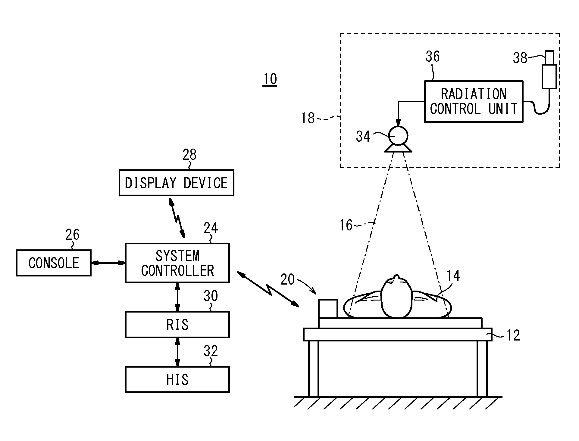
[0326]In the above embodiment and Modified Examples 1 and 2, in a case where the radiographic image capturing process is performed multiple times, the user operates the radiation switch 38 to emit the radiation 16 from the radiation source 34 multiple times. In this case, the radiation 16 may be continuously emitted from the radiation source 34 over a predetermined time, and the electronic cassette 20 may act to perform the radiographic image capturing process multiple times in the predetermined time. The user can operate the input device of the radiation control unit 36 to set the predetermined time. The radiation control unit 36 controls the radiation source 34 to emit the radiation 16 for the setup predetermined time.

[0327]FIG. 19 is a time chart of the operation of the electronic cassette 20 in Modified Example 3. In the electronic cassette 20, the first readout control part 130 repeatedly executes the scan mode until the emission of the radiation 16. When the emission of the ra...


PUM


Abstract

A radiological image-capturing device includes: a first read control section that executes a first read mode in which electric signals stored in a plurality of pixels are read out simultaneously in units of a plurality of rows; and an emission-start determining section that determines that the emission of radiation from a radiation source onto an image-capturing panel has started when the values of the electric signals read by the first read control section have become greater than an arbitrarily settable threshold. If it is determined by the emission-start determining section that the emission of said radiation has started, the first read control section terminates the reading of the electric signals, and thereby brings the image-capturing panel into an exposure state.

Description

CROSS-REFERENCE TO RELATED APPLICATIONS AND PRIORITY CLAIM[0001]This application is a Continuation of International Application No. PCT / JP2011 / 062518 filed on May 31, 2011, which was published under PCT Article 21(2) in Japanese, which is based upon and claims the benefit of priority from Japanese Patent Applications No. 2010-161927 filed on Jul. 16, 2010, No. 2010-161925 filed on Jul. 16, 2010, No. 2010-161924 filed on Jul. 16, 2010, No. 2010-161922 filed on Jul. 16, 2010, No. 2010-161917 filed on Jul. 16, 2010, No. 2010-161915 filed on Jul. 16, 2010, No. 2010-164829 filed on Jul. 22, 2010, No. 2010-165981 filed on Jul. 23, 2010 and No. 2010-170055 filed on Jul. 29, 2010, the contents all of which are incorporated herein by reference.TECHNICAL FIELD[0002]The present invention relates to a radiographic (radiological) image capturing apparatus, a radiographic image capturing system, a radiographic image capturing method, and a program for forming an image from a radiation transmitted...

Claims


Application Information

Patent Timeline
IPC IPC(8): G01N23/04
CPCH01L27/14663H04N7/18H04N5/32H04N5/374H04N5/378G01N23/04H04N5/217G01T1/247A61B6/4266A61B6/548A61B6/4233A61B6/467G06T7/0012H04N5/37213H01L27/14676H04N5/77H04N9/8205H04N23/81H04N25/76H04N25/75H04N25/713
Inventor KITANO, KOUICHIOHTA, YASUNORINOMA, KENTAROIWAKIRI, NAOTOSHIMADA, KATSUMIWATANABE, KEITASHIMIZUKAWA, SHOUIWAMOTO, TAKAHIRO
Owner FUJIFILM CORP
Why Eureka
Try Eureka