Image forming apparatus

Inactive Publication Date: 2013-06-06
CANON KK
View PDF6 Cites 6 Cited by
  • Summary
  • Abstract
  • Description
  • Claims
  • Application Information

AI Technical Summary

Benefits of technology

The present patent is about an image forming device that can correct any changes in the photosensitive member caused by variations in film thickness or sensitivity. The device is designed to have a simple configuration.

Problems solved by technology

Thus, when the method is applied to a color image forming apparatus using a plurality of photosensitive members, there can be disadvantageous in miniaturization of the apparatus and in reduction of costs.
This may affect a life of the photosensitive member.
As discussed in Japanese Patent Application Laid-Open No. 2002-296853, when the method for controlling the exposure amount of the non-image portion according to a change amount of the photosensitive member film thickness calculated from the photosensitive member rotational speed is used, it is difficult to correct potential fluctuation caused by variations of film thickness or sensitivity unique to each photosensitive member (obtained when the photosensitive member is brand-new).

Method used


Image

  • Image forming apparatus
  • Image forming apparatus
  • Image forming apparatus

Examples


Embodiment Construction

[0027]Various exemplary embodiments, features, and aspects of the disclosure will be described in detail below with reference to the drawings.

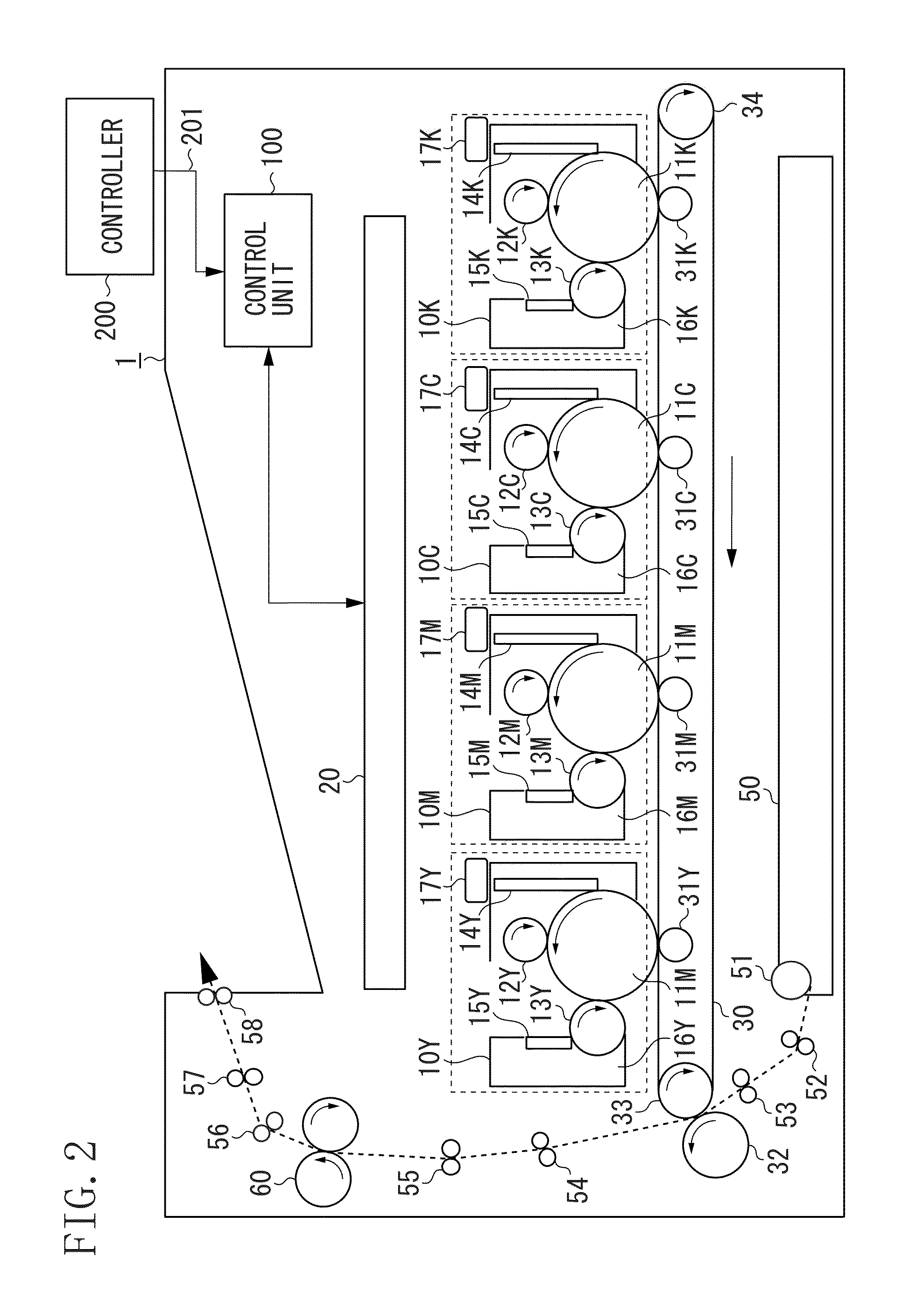
[0028]FIG. 2 is a schematic sectional view illustrating an image forming apparatus according to a first exemplary embodiment.

[0029]In FIG. 2, an image forming apparatus 1 is a laser beam printer that uses an electrophotographic process. The image forming apparatus 1 forms an image corresponding to image data (electric image information) input from a printer controller (external host apparatus) 200 connected to a printer control unit 100 via an interface 201 on a sheet P as a recording medium to output an image formed product. The control unit 100, which is configured to control an operation of the image forming apparatus, transfers various electric information signals to and from the printer controller 200. The control unit 100 also controls processing of electric information signals input from various process devices and sensors, processing o...


PUM


Abstract

An image forming apparatus includes a photosensitive member, a charging unit configured to charge the photosensitive member, an exposure unit configured to expose the charged photosensitive member with first laser power to generate a non-image portion potential in a non-image portion of the photosensitive member and with second laser power different from the first laser power to generate an image portion potential in an image portion of the photosensitive member, a development unit configured to form a developer image by applying a developer to a portion of the image portion potential, a control unit configured to control the laser power of the exposure unit, and a storage unit configured to store information about the photosensitive member obtained when the photosensitive member is brand-new. The control unit changes an output of the first laser power according to the information about the photosensitive member stored in the storage unit.

Description

BACKGROUND OF THE INVENTION[0001]1. Field of the Invention[0002]The present disclosure generally relates to an image forming apparatus such as a copying machine or a printer of an electrophotographic type.[0003]2. Description of the Related Art[0004]Conventionally, in some electrophotographic image forming apparatuses, a contact charging device, which employs a method in which a voltage is applied to a charging member abutting on a photosensitive member to charge the photosensitive member, has been put to practical use, because of its advantages of lower ozone use and lower power consumption. In particular, a device of the roller charging type using a charging roller as a charging member has been in wide use because of its excellent charging stability.[0005]In the contact charging device of the roller charging type, when a certain level of voltage (charging start voltage Vth) is applied to the charging roller, a surface potential of the photosensitive member starts to rise. Thereaft...

Claims


Application Information

Patent Timeline
IPC IPC(8): B41J2/435
CPCG03G15/043G03G15/22G03G21/1889G03G15/55G03G15/5037
Inventor HASEGAWA, HIDEAKIWATANABE, YASUNARISHIMURA, MASARUKOBAYASHI, SHINSUKENANATAKI, HIDEOKATAGIRI, SHINJITOYOIZUMI, KIYOTO
Owner CANON KK
Why Eureka
Try Eureka