Supercharge Your Innovation With Domain-Expert AI Agents!

Turbine impeller comprising blade with squealer tip

a technology of turbine impeller and blade, which is applied in the direction of blade accessories, machines/engines, mechanical apparatus, etc., can solve the problems that the fluid passing through the gap between the end of the blade and the shroud cannot contribute to the production of energy via the revolution of the turbine impeller at all, and waste fluidic energy of the fluid through the gap, so as to reduce the thermal damage of the blade, prevent the formation of hot spots, and high efficiency

Active Publication Date: 2013-06-06
HANWHA AEROSPACE CO LTD
View PDF22 Cites 14 Cited by
  • Summary
  • Abstract
  • Description
  • Claims
  • Application Information

AI Technical Summary

Benefits of technology

The invention is a turbine impeller with blades that are designed to prevent damage from high temperatures in the blade. This results in higher efficiency performance of the turbine.

Problems solved by technology

However, the fluid passing through the gap between the end of the blade and the shroud cannot contribute the production of energy via revolution of the turbine impeller at all.
Therefore, the fluidic energy of the fluid through gap is wasted.

Method used


Image

  • Turbine impeller comprising blade with squealer tip
  • Turbine impeller comprising blade with squealer tip
  • Turbine impeller comprising blade with squealer tip

Examples


Embodiment Construction

[0027]Reference will now be made in detail to embodiments, examples of which are illustrated in the accompanying drawings, wherein like reference numerals refer to the like elements throughout. In this regard, the present embodiments may have different forms and should not be construed as being limited to the descriptions set forth herein. Accordingly, the embodiments are merely described below, by referring to the figures, to explain aspects of the present description.

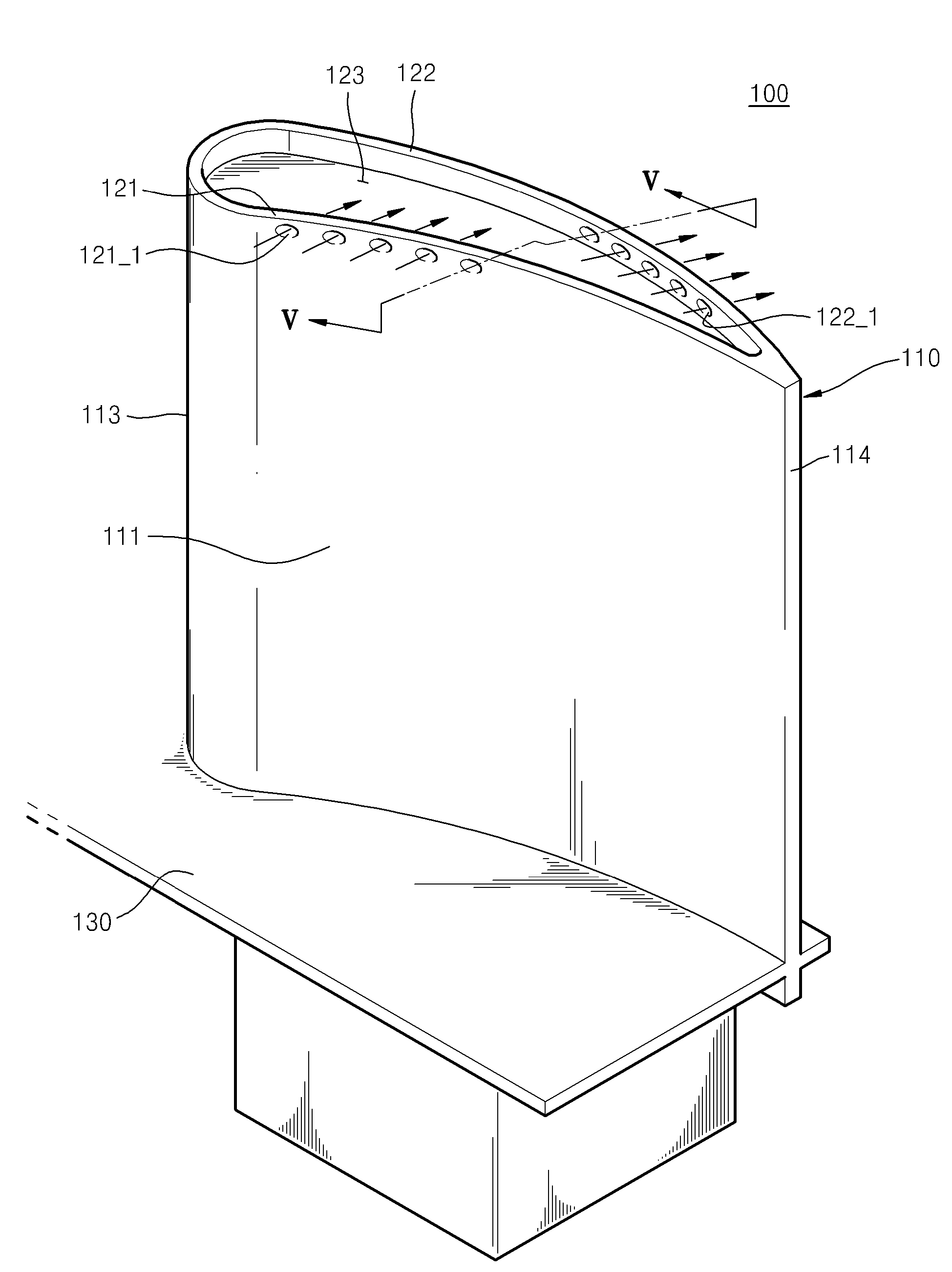
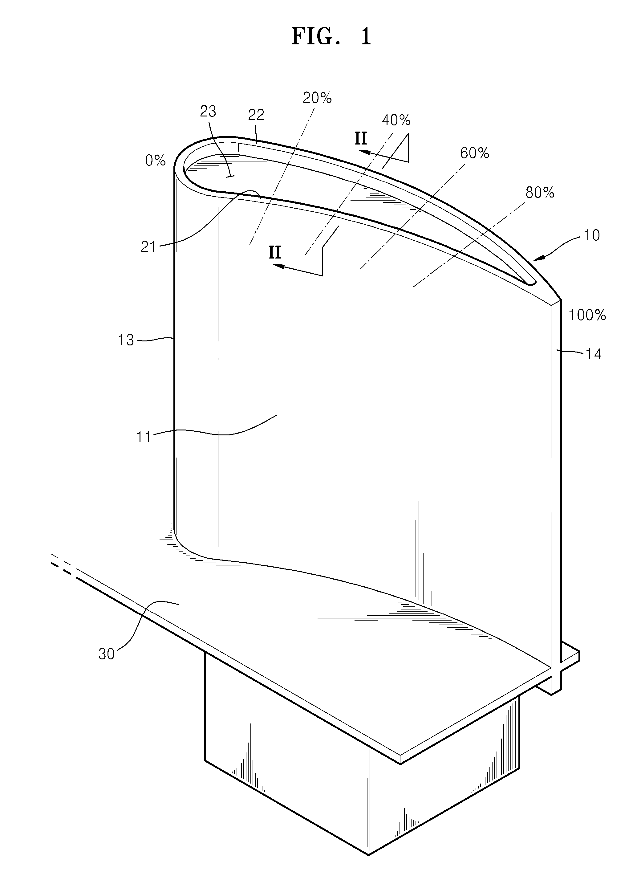
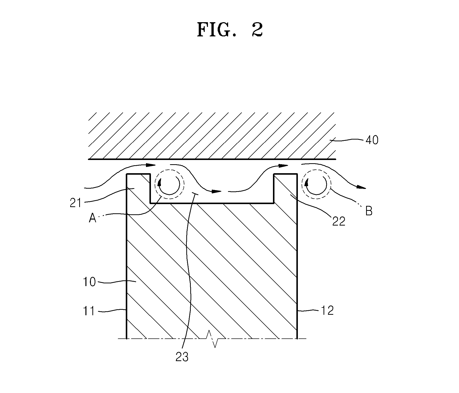
[0028]FIG. 1 is a diagram partially showing a turbine impeller having a blade 10 with thereat squealer tips 21 and 22 in the related art. FIG. 2 is a diagram showing the blade 10 shown in FIG. 1 viewed in a direction along a line II-II and showing flow of a fluid via a partial cross-section of the shroud 40. FIGS. 3A, 3B, and 3C are diagrams showing flows around at 20%, 40%, and 60% cross section along an axial axis from a leading edge 13 to a trailing edge 14 of the blade 10 shown in FIG. 1, respectively.

[0029]FIG. 1...


PUM


Abstract

A turbine impeller including a rotor; a blade extending from the rotor from a first end of the blade; and a squealer tip provided at a second end opposite to the first end of the blade, wherein at least one perforated portion penetrates through the squealer tip.

Description

RELATED APPLICATIONS[0001]This application claims the benefit of Korean Patent Application No. 10-2011-0129907, filed on Dec. 6, 2011 in the Korean Intellectual Property Office, the disclosures of which are incorporated herein by reference in their entirety.BACKGROUND[0002]1. Field[0003]Apparatuses consistent with one or more exemplary embodiments relate to a structure of a turbine impeller including a blade with a squealer tip for preventing thermal damage and for featuring high efficiency.[0004]2. Description of the Related Art[0005]A turbine is a device for producing power by using an energy generated as a high temperature and high pressure fluid flows in the turbine and expands. In the related art, the turbine includes one or more turbine impellers. Each turbine impeller includes a rotor located at the center and a plurality of blades extending in a long shape from a surface of the rotor. The rotor and the blades that are formed as a single body is accommodated in a shroud. The ...

Claims


Application Information

Patent Timeline
Patent Type & Authority Applications(United States)
IPC IPC(8): F01D5/14
CPCF01D5/20F01D5/145F01D5/02F01D5/14F01D25/00
Inventor LIM, CHAN-SUN
Owner HANWHA AEROSPACE CO LTD
Features
  • R&D
  • Intellectual Property
  • Life Sciences
  • Materials
  • Tech Scout
  • Unparalleled Data Quality
  • Higher Quality Content
  • 60% Fewer Hallucinations
Learn More