Earth-boring tools, methods of forming earth-boring tools, and methods of repairing earth-boring tools

a technology of earth-boring tools and earth-boring tools, which is applied in the field of earth-boring tools and to the method of fabricating earth-boring tools, can solve the problems of poor repairability, poor fracture toughness, and/or low dimensional precision, and achieves the effect of improving the dimensional precision of the tool, and improving the dimensional precision

Active Publication Date: 2013-06-13
BAKER HUGHES INC
View PDF8 Cites 21 Cited by
  • Summary
  • Abstract
  • Description
  • Claims
  • Application Information

AI Technical Summary

Problems solved by technology

Conventional metal-matrix composite materials (and thus, bit bodies or tools formed from such materials) may have some desirable mechanical and thermal

Method used


Image

  • Earth-boring tools, methods of forming earth-boring tools, and methods of repairing earth-boring tools
  • Earth-boring tools, methods of forming earth-boring tools, and methods of repairing earth-boring tools
  • Earth-boring tools, methods of forming earth-boring tools, and methods of repairing earth-boring tools

Examples


embodiment 1

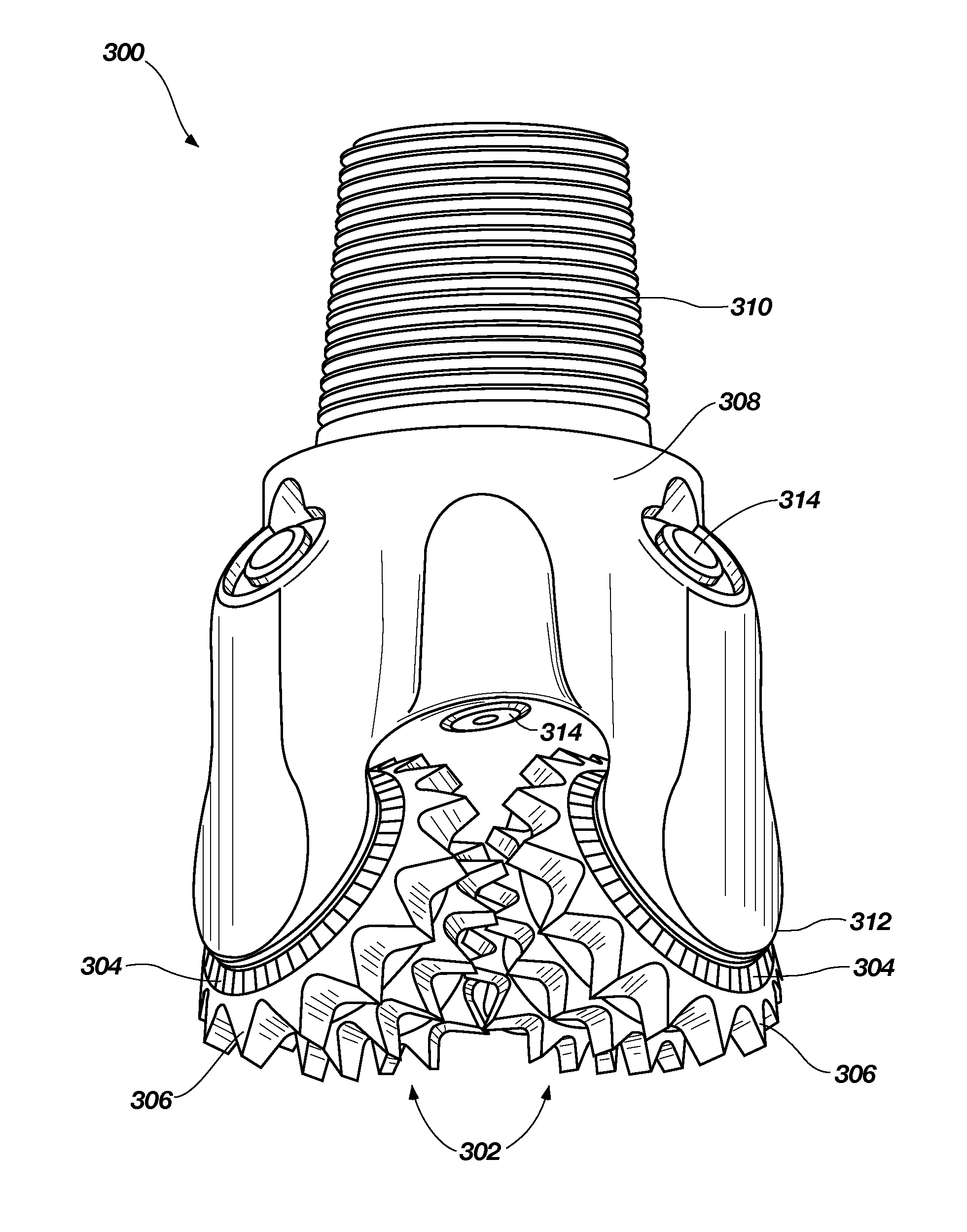
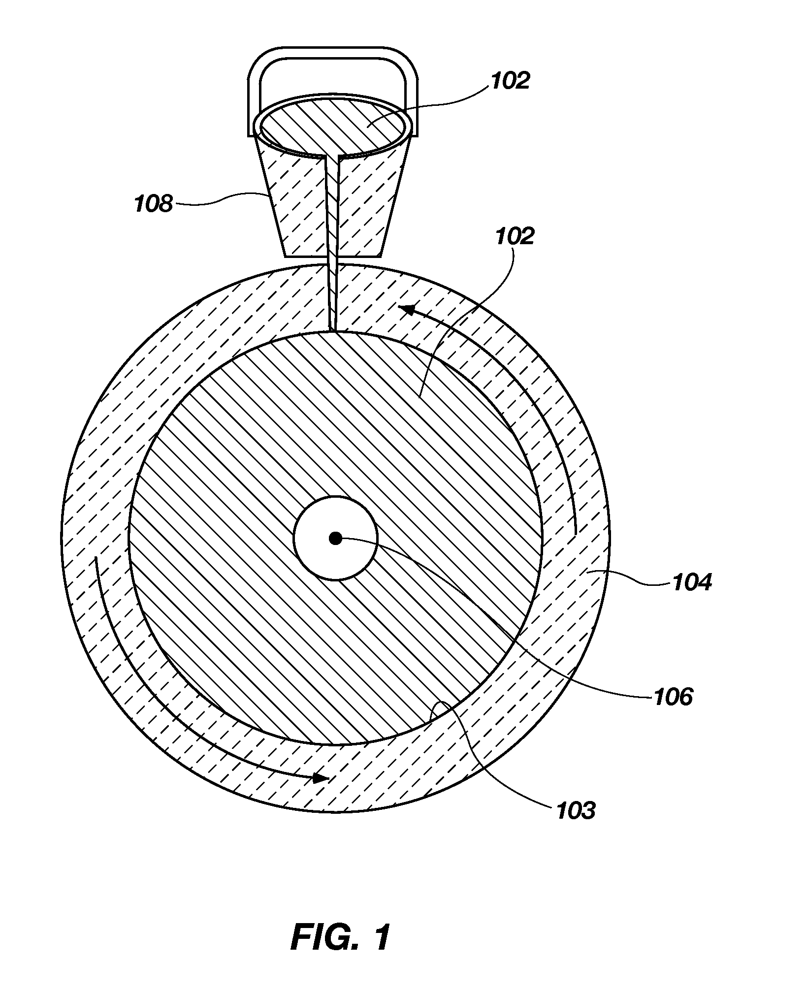
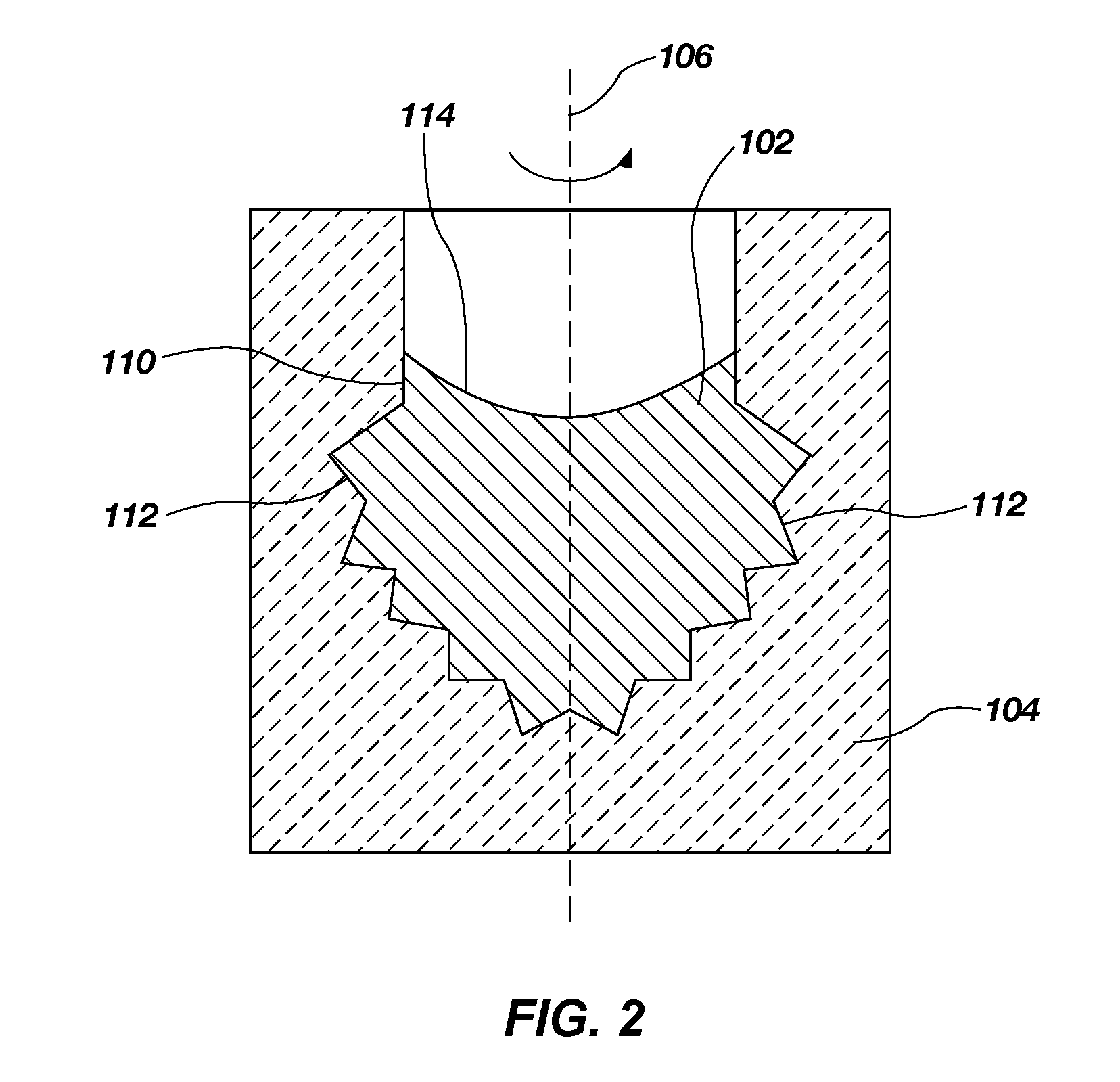
[0049] A method of forming an earth-boring tool, comprising introducing a first metal into a die configured to define at least a portion of an earth-boring tool, rotating the die while the first metal is in a molten state within the die to generate centrifugal forces on the molten first metal within the die, and cooling the first metal in the die while the die is rotating and solidifying the first metal from the molten state to form at least a portion of the earth-boring tool.

embodiment 2

[0050] The method of Embodiment 1, wherein introducing the first metal into the die comprises pouring the first metal into the die in the molten state.

embodiment 3

[0051] The method of Embodiment 2, wherein pouring the first metal into the die comprises pouring the first metal into the die while the die is rotating

[0052]Embodiment 4: The method of any of Embodiments 1 through 3, wherein the first metal comprises a maraging steel alloy.


PUM

PropertyMeasurementUnit
Temperatureaaaaaaaaaa
Forceaaaaaaaaaa
Centrifugal forceaaaaaaaaaa

Abstract

A method of forming an earth-boring tool includes introducing metal into a die, rotating the die to generate centrifugal forces on the metal, and cooling the metal in the rotating die. A rotary drill bit may include a unitary, centrifugally cast bit body including an integral shank, at least one blade, and at least one cutting element on the blade. A rotary drill bit or a roller cone may include a first centrifugally cast material and a second centrifugally cast material. Another rotary drill bit includes a bit body comprising a maraging steel alloy. A method of forming a rotary drill bit may include disposing cutting elements on a rotary drill bit comprising maraging steel and aging the rotary drill bit to form at least one intermetallic precipitate phase. Methods of repairing a rotary drill bit include annealing and aging at least a portion of a rotary drill bit.

Description

FIELD[0001]The present disclosure relates to earth-boring tools and to methods of fabricating earth-boring tools.BACKGROUND[0002]Earth-boring tools for forming boreholes in subterranean earth formations, such as for hydrocarbon production, carbon dioxide sequestration, etc., generally include a plurality of cutting elements secured to a body. For example, fixed-cutter earth-boring rotary drill bits (also referred to as “drag bits”) include cutting elements fixed to a bit body of the drill bit. Similarly, roller-cone earth-boring rotary drill bits may include cones mounted on bearing pins extending from legs of a bit body such that each cone is capable of rotating about the bearing pin on which it is mounted. A plurality of cutting elements may be provided on each cone of such a drill bit.[0003]Bit bodies may be formed of metal-matrix composites having a continuous phase and a dispersed phase. The continuous phase may be a metal or an alloy, such as a copper alloy, steel, cobalt, a c...

Claims


Application Information

Patent Timeline
IPC IPC(8): E21B10/00C21D9/22B22D25/02B22D19/16E21B10/36B22D13/00
CPCC21D6/001C21D2211/004C21D2211/008B22D13/00B22D19/16C22C38/12C21D9/22E21B10/00E21B10/36C22C38/105B22D25/02Y02P10/122B22D13/04B22D19/06C21D1/18C22C38/08C22C38/14B22D13/02B22D19/00E21B10/42E21B10/55
Inventor CHENG, XIAOMIN CHRISSULLIVAN, ERIC C.TRINH, TU TIEN
Owner BAKER HUGHES INC
Why Eureka
Try Eureka