Mechanical coupling in a draftgear

a technology of mechanical coupling and draftgear, which is applied in the direction of railway couplings, railway components, transportation and packaging, etc., can solve the problems of oscillation of the hooking rod, preventing its movement, and impairing the function of the piston, so as to reduce the friction between the leaf spring and the hooking rod, compact and space-saving design, and reduce the effect of friction

Active Publication Date: 2013-06-13
DELLNER COUPLERS AB
View PDF12 Cites 8 Cited by
  • Summary
  • Abstract
  • Description
  • Claims
  • Application Information

AI Technical Summary

Benefits of technology

[0012]In order to reduce the friction between the leaf spring and the hooking rod, the free end of the leaf spring may be formed with a radius that abuts in sliding contact against the hooking rod. For the same reasons, the abutment surface of the leaf spring may carry a wear protection in the form of a covering or a sliding block.
[0013]In order to distribute the wear over a larger surface of the hooking rod, it may be advantageous to arrange said radius in a plane that intersects the longitudinal axis of the hooking rod at an oblique angle, whereby the contact between the hooking rod and the leaf spring is in the form of a contact line running obliquely across the width of the hooking rod.
[0014]The attached end of the leaf spring may be attached to the collar whereby a compact and space-saving design is achieved. For the same reasons, the collar may advantageously be formed on a bracket carried on a housing serving for the bearing of a releasing device formed as a spring-loaded rod.

Problems solved by technology

Furthermore, the lug of the hooking rod is formed with a tilted front edge, which slides across the collar in the hooking motion and causes an oscillation of the hooking rod when the lug passes the collar.
A disadvantage of this design is that penetration particles, moisture and corrosion may impair the function of the piston and prevent its motion.
This disadvantage may cause the hooking up of the coupling not to occur.

Method used


Image

  • Mechanical coupling in a draftgear
  • Mechanical coupling in a draftgear
  • Mechanical coupling in a draftgear

Examples


Embodiment Construction

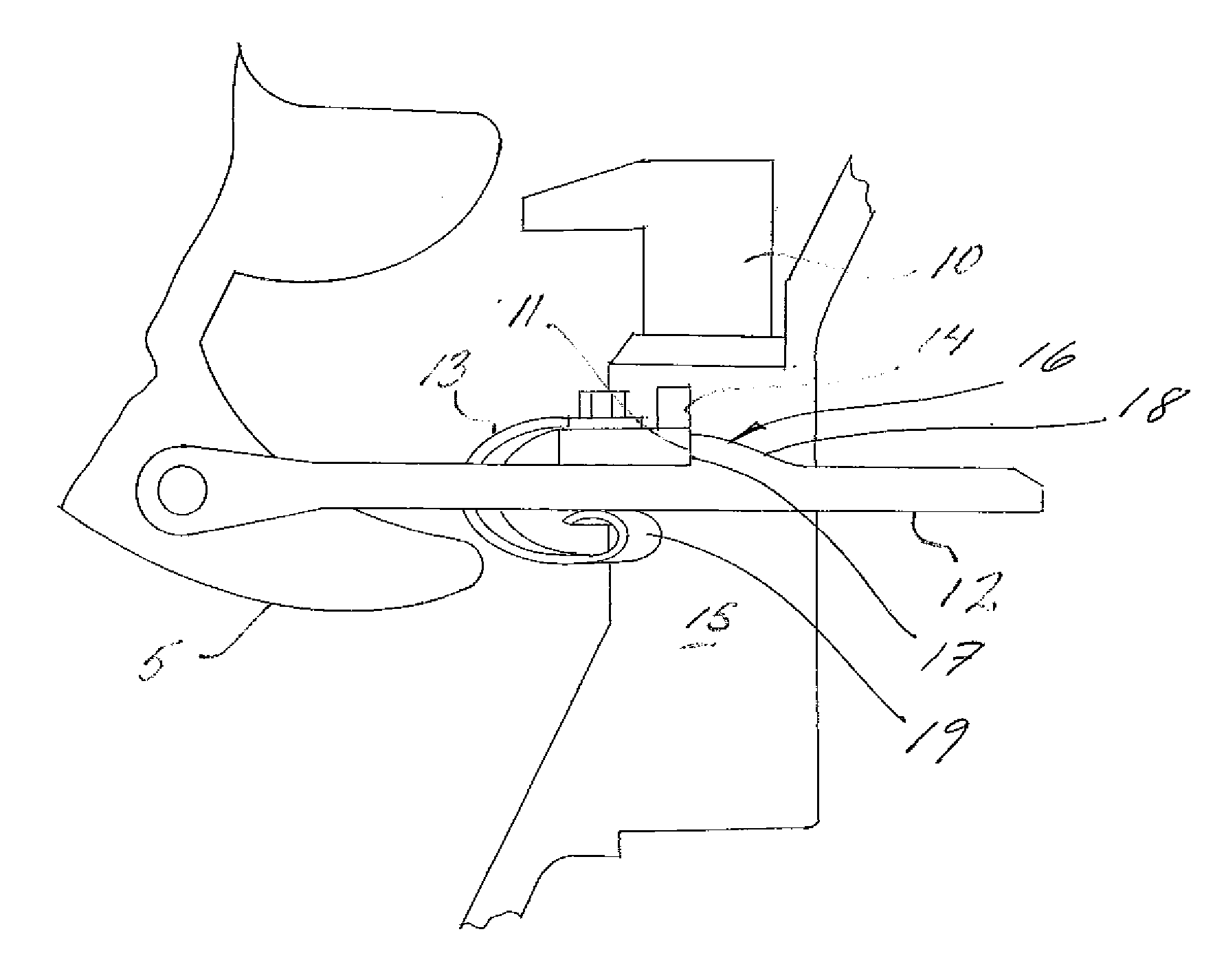
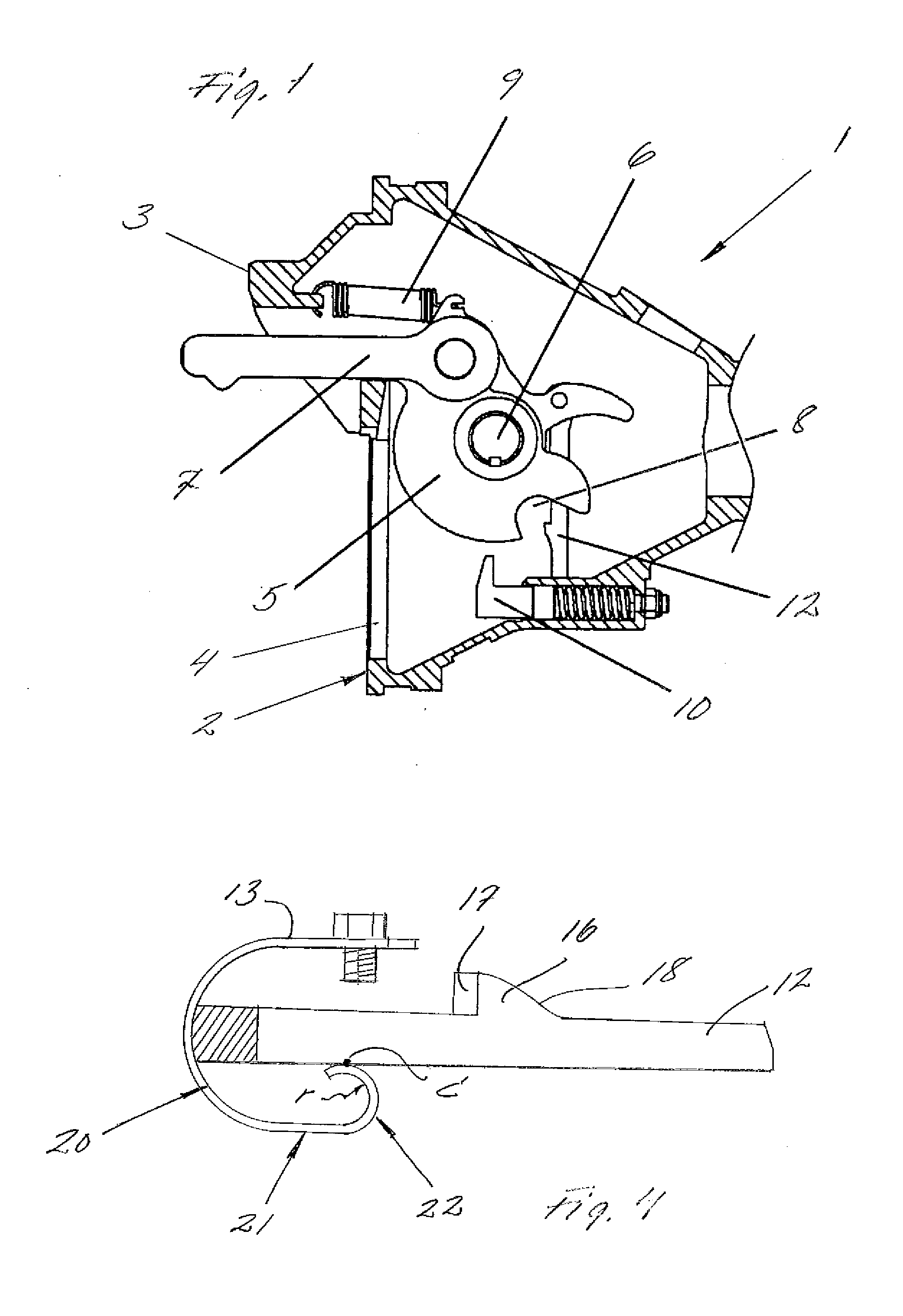
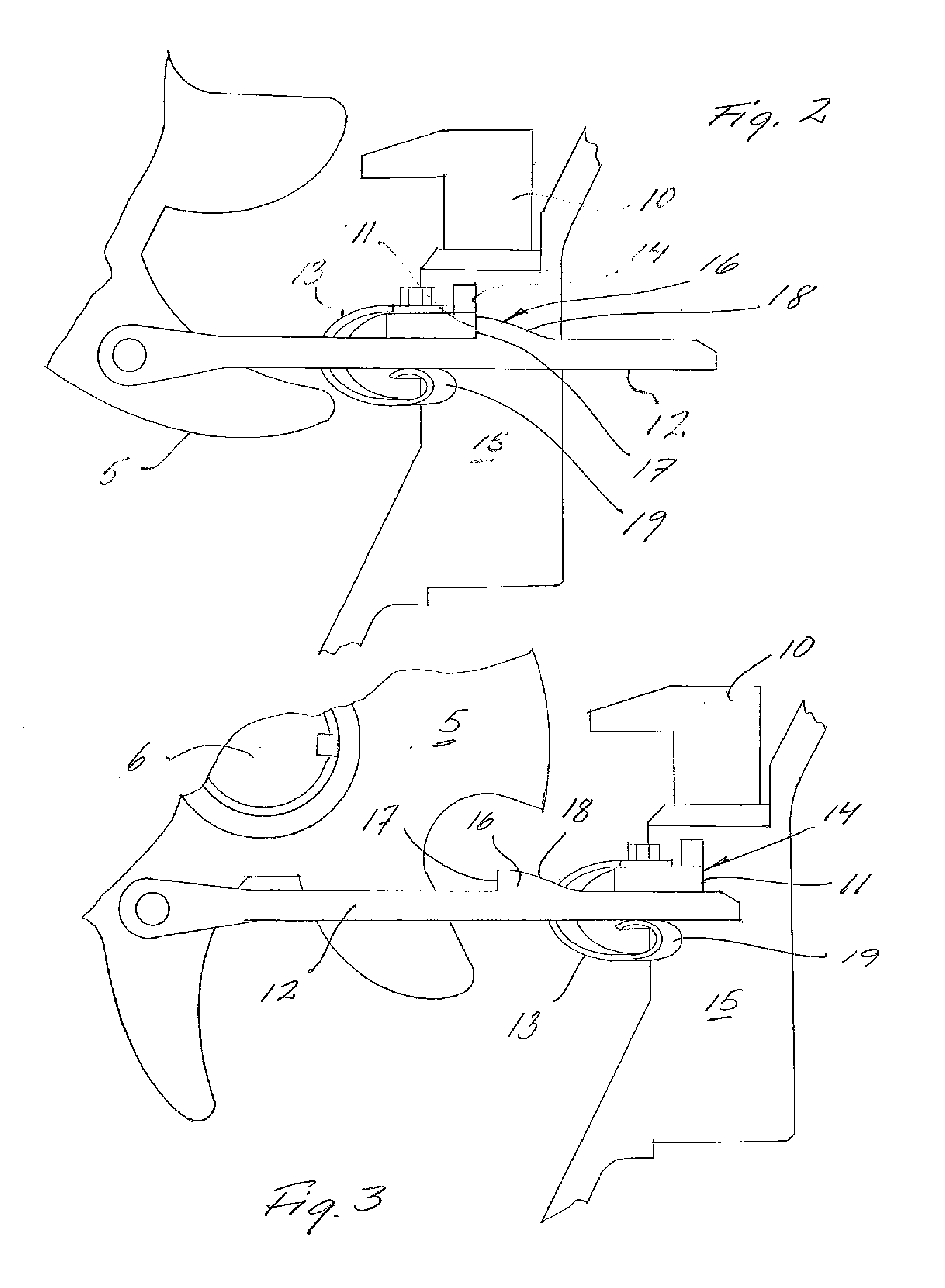
[0022]FIG. 1 shows a coupler head 1, which has a front plate 2 having a projecting guide cone 3 and an opening 4 intended for the receipt of the guide cone (not shown) of a meeting coupler head upon coupling of the draftgears. In the coupler head, there is contained a mechanical coupling comprising a central plate 5, which is turnably mounted on a main shaft 6 mounted in the coupler head. A coupling link 7 is pivoted in the central plate, which in its periphery has a recess 8 for hooking on to a corresponding coupling link of a meeting draftgear. A tension spring 9 biases the central plate toward the coupled position shown in FIG. 1. The reference numeral 10 designates a releasing device 10 that, by the guide cone of a meeting coupler head, is actuated to detach a hooking mechanism described in more detail below, reference being made to FIGS. 2 and 3. For the sake of completeness, it should be mentioned that, in the coupler head, there is typically arranged a driven piston effective...


PUM


Abstract

A mechanical coupling, particularly in a draftgear in rail vehicles, includes a central plate (5) turnably mounted in a coupler head and having a link (7) pivoted in the same, and including a hooking mechanism for detachable hooking up of the central plate and the link in the non coupled position of the coupling, and a releasing device (10) for the automatic detachment of the hooking mechanism upon coupling. The hooking mechanism includes a hooking rod (12) pivotally connected with the central plate, which rod, by a lug (16), clutches a collar (11) arranged in the coupler head and, upon activation of the releasing device, detaches from the collar. A leaf spring (13) is arranged in the coupler head in order to, in abutment against the hooking rod, force the same, under the bias from the spring, to be pressed against the collar in the hooked up and disengaged positions.

Description

TECHNICAL FIELD OF THE INVENTION[0001]The invention relates to a mechanical coupling in a draftgear, particularly a draftgear in rail vehicles. More precisely, the invention relates to an improved mechanical coupling of the type comprising a central plate turnably mounted in a coupler head and having a coupling link pivoted in the same, and including a hooking mechanism for detachable hooking up of the central plate and the link in the non coupled position of the coupling, as well as including a releasing device for the automatic detachment of the hooking mechanism upon coupling, wherein the hooking mechanism comprises a hooking rod pivotally connected with the central plate, which rod, by a lug, clutches a collar arranged in the coupler head and, upon activation of the releasing device, is detached from said collar.BACKGROUND AND PRIOR ART[0002]Couplings of this type are found in draftgears arranged for the automatic coupling of locomotives and cars. The couplings are contained in ...

Claims


Application Information

Patent Timeline
Patent Type & Authority Applications(United States)
IPC IPC(8): B61G3/16
CPCB61G3/16
Inventor WESTMAN, ANDERSHISWALS, FREDRIK
Owner DELLNER COUPLERS AB
Why Eureka
Try Eureka